


Testing
OOvveerrvviieeww
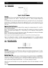
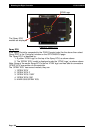
The Boom Section Drive outputs from the controller simply apply a 12volts signal to Pin-3 of
the section valve to OPEN. 0volts CLOSES the valve. The 3-wire section valves require constant
12volt (Pin-1) and constant Gnd (Pin-2) as well as the 12v Signal to Pin-3.
SSeeccttiioonn
VVaallvvee
DDrriivvee
TTeesstt
Set controller to Manual mode.
1. Using a digital Multimeter set to 20vdc connect probes to Pin-1 and Pin 2 on section one
Valve tail. Confirm 12volts.
Repeat this for all section valve tails.
22..
SSwwiittcchh
MMaasstteerr
SSwwiittcchh
OONN..
Using a digital Multimeter set to 20vdc connect probes to Pin-2 and Pin-3 on section one Valve
tail. Turn on Section 1. Confirm 12volts on Pin 3. Turn Section 1 OFF and confirm 0volts.
Repeat this process for all section valves.
OOvveerrvviieeww
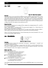
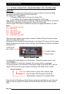
The proportional drive output allows control of PWM Hydraulic Solenoid valves.
Pin- 1 provides a constant 12volt supply to the coil while Pin-3 delivers a "Switched Gnd
PWM" signal.
PPrroopp
O
Ouuttppuutt
TTeesstt
• Connect an automotive test light between Pin-1 and Pin-3.
• Switch a tank ON and Master Switch ON.
•With the controller set to Manual press and hold the Increase button. The light
should glow progressively brighter in 1 second time increments to full brightness.
• Stop pressing the Increase Button. The light should maintain the current brightness.
• Press the Decrease Button. The Light should become progressively dimmer.
Page 102
V1.98 21/06/06
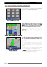
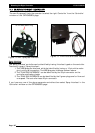
19.5 3 WIRE SECTION VALVES
19.6 PWM REGULATOR VALVE
FFiigguurree
7711::
33-wwiirree
ccoonnnneeccttoorr
FFiigguurree
7722::
PPWWMM
RReegguullaattoorr
VVaallvvee
ccoonnnneeccttoorr