


Major Topic Heading
Installation of Spray ECU 30S KEE Sprayer Kits
Pressure
Sensor
installation
and
connection
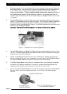
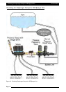
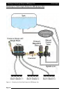
1. Mount the Pressure Sensor (A092) either upright or horizontal and support the brass
gauge saver. To properly measure Spray Line operating pressure the Pressure Sensor
must be positioned between the flow meter and the section valves. The supplied
Pressure Sensor is a 5 Bar (72 psi) pressure sensor.
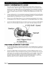
2. Connect the Pressure Adaptor Harness (H1125) to the connector labeled Pressure Sensor 1
on the Sprayer Harness.
3. Undo the two (2) nuts on top of the Pressure Sensor.
4. Place the two ring terminals on the Pressure Adaptor Harness onto the terminals on the
Pressure Sensor. It doesn't matter which way around the terminals are attached to the
Pressure Sensor.
5. Once the ring terminals are placed on the Pressure Sensor terminals replace the two (2)
nuts and tighten the nuts securely.
1.2.3 Installing
the
Valve
Harness
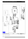
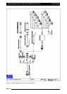
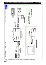
1. The Valve Harness continues from the connector on the Sprayer Harness and connects to
the Section and Dump Valves on the Sprayer.
2. The Valve Harness normally contains connectors for the section valves; either they are; ‘3
Wire section valves’, ‘2 Wire Section Valves’ or ‘solenoid valves’.
See below for an
explanation of the different types of section valves..
Note: If the Valve Harness has an Arag Interface box incorporated into the harness, then
the Dump Valve plug will be on the Valve Harness.
5. The typical Valve Harness has the following connectors, they are labeled as follows:
DDuummpp
11-
connects to the Dump Valve.
SSeeccttiioonn
XX-
connects to the Section Valves. ‘X’ represents the section number.
SSpprraayyeerr
HHaarrnneessss-
connects to the Sprayer Harness.
3. There are different Valve Harness depending on which type of section valves on fitted on
the sprayer.
Note: If the Valve looms need to be re-terminated because the connectors are different to
the section valves being connected to, then make sure the ‘Sprayer Harness’ is
disconnected from the ‘Tractor Harness’. Otherwise damage to the Spray ECU
wwiillll
occur if
the wires are shorted out during the installation.
4. Secure the Valve Harness away from moving, hot or sharp objects to avoid chaffing and
wear, using the cable ties provided.
6. Connect the Valve Harness to the Sprayer Harness.
Page 20
V1.98 21/06/06