


Installation of Spray ECU 30S KEE Sprayer Kits
Connecting
to
Flow
Meter
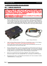
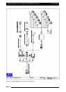
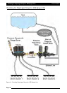
1. The flow meter (not supplied) is installed between the regulator valve and the section
valves. The flow meter will be installed so that it measures ONLY the quantity of liquid
being delivered to the spray line.
Note: There must be no return line to tank or pump after the flow meter.
2. Connect the flow meter 3-pin connector to the 3-pin connector marked Flow Meter 1
on the Sprayer Harness.
Note: The flow meter may require a connector change to attach to the 3-pin connector
marked Flow Meter 1 on the Sprayer Harness. Refer to the flow meter manufacturer's
specifications for correct pin allocation. Care should be taken when replacing these
connectors not to damage the Sprayer Harness or flow meter and connectors should
be fully circuit tested prior to installation.
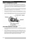
3. Most flow meters have a label on the meter body that shows the flow meter
Calibration Factor in pulses/volume. For example: '645 ppl' (pulses per litre) or 2441
ppg (pulses per gallon). This value is the Calibration Factor and will be required to be
entered into the sprayer software setup. This means the flow meter sends 645 pulses
to the Spray ECU for every litre (or 2441 pulses for every gallon) of liquid that passes
through the flow meter.
4. For connection to a Raven flow meter: The value marked on the label represents
pulses/10 units of liquid. Divide this number by 10 for the correct value to enter as the
Calibration Factor into the Sprayer Software Setup.
Connecting
to
the
Regulator
Valve
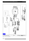
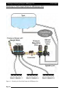
1. The regulator valve (not supplied) is a motorized flow control valve used to maintain
the product flow to the section valves. It will be situated between the pump and the
flow meter.
2. All bypass or agitation return lines that return to tank must be taken before the
regulating valve, so there is no return path after the regulating valve and the flow
sensor.
3. Using the Regulator Valve Adaptor Harness (A802) connect the regulator valve's 2-pin
connector to the 2-pin connector marked REG Valve 1 on the Sprayer Harness.
Note: The regulator valve may require a connector change to attach to the 2-pin
connector marked REG Valve 1 on the Sprayer Harness. Refer to the regulator valve
manufacturer's specifications for correct pin allocation. Care should be taken when
replacing these connectors not to damage the Sprayer Harness or regulator valve and
connectors should be fully circuit tested prior to installation.
4. When you test the sprayer with water you may find that the regulator valve works in
the opposite direction than is required. For example the pressure increases when it
should decrease. You can set the "Reverse Valve Direction" in the Sprayer Setup
software to remedy this.
Page 19
V1.98 21/06/06