


Installation of Spray ECU 30S KEE Sprayer Kits
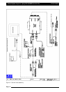
Single
Line
Install
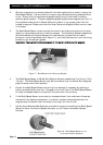
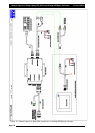
5. Connect the connectors marked Section X (‘X’ represents the section number) to the
correct section valves. Section 1 connects to the section valve on the far left. Section 2
connects to the next section valve and so forth until all the section valves are connected
to the Valve Harness.The section valve with the highest number will operate the
boom section on the far right. If there are too many connectors for the section valves,
then as a general rule use the connectors with the lowest numbers first.
6. Cable-tie the spare connectors to the Valve Harness.
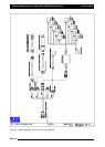
Dual
Line
Install
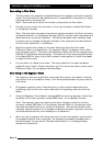
7. Connect the connectors using the lowest numbers first that operate the primary spray
line (Line A). Starting with Section 1 to operate the section on the FAR LEFT of the
spray line, when facing forward finishing with the highest number section valve on
Line A to operate the FAR RIGHT.
8. Connect the connectors to the section valves which are going to operate the secondary
line (Line B). Starting the lowest number on the Line B to operate the FAR LEFT boom
section, finishing with the highest number boom section on the Line B to operate the
FAR RIGHT boom section.
Note: If the Valve Harness needs the connectors replaced to suit the valves connectors
then make sure the Sprayer Harness is disconnected from the Tractor Harness.
Otherwise damage to the Spray ECU will occur if the wires are shorted out during this
procedure.
Connecting
to
the
Dump
Valve
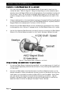
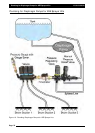
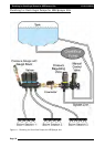
6. The dump valve (not supplied) must be located between the pump and the flow meter.
7. The dump valve is activated when all sections are switched OFF, or the Master Switch
is switched OFF, therefore all the flow is diverted back to the tank.
8. Connect the ARAG connector, labeled Dump 1 to the dump valve.
Note: During setting up of the sprayer the wires in the ARAG connector may have to
be swapped, if the dump valve is going in the wrong direction.
9. If the Dump Valve connector is on the Sprayer Harness, then an adaptor will be
required to connect the 4-Pin Weather Pack to the Dump Valve. Connect the correct
adaptor to the Dump Valve from the following adaptors:
a) A2266- if connecting to a 2-wire dump valve and 12v is applied to the dump
valve when the Master switch is OFF.
b) A2267- if connecting to a solenoid valve, with 6mm spade terminals and 12v
is applied to the dump valve when the Master switch is OFF.
c) A2268- if connecting to a 3-wire dump valve and 12v is applied to the dump
valve when the Master is OFF.
d) A2269- if connecting to 3-wire dump valve and 12v is applied to the dump
valve when the Master is ON.
Page 21
V1.98 21/06/06