


Installation of Spray ECU 30S KEE Sprayer Kits
11..22 IInnssttaallllaattiioonn
ooff
SSpprraayy
EECCUU
3300SS
KKEEEE
SSpprraayyeerr
KKiittss
All KEE Sprayer kits come with their installation guide which is specific to each kit,
please use the specific installation guide which come with your KEE Sprayer kit. This
section is a general guide for an installation of all KEE Spray ECU 30S Sprayer kits.
This installation guide will take the installer through the following steps:
1.2.1 Installing the Tractor Harness
1.2.2 Installing the Sprayer Harness
1.2.3 Installing the Valve Harness
1.2.1 Installing
the
Tractor
Harness
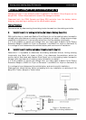
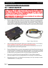
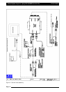
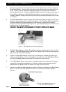
1. Connect the Tractor Harness to the 37-Pin connector marked CONNECTOR 1, on the
Spray ECU. Figure 4 shows the in-cabin assembly showing Spray ECU, Power/Comms
Harness, Switchbox and Tractor Harness.
2. Run the Tractor Harness from the Spray ECU to the drawbar or the back of the vehicle.
Ensure that the Tractor Harness is tied away from moving, hot or sharp objects. Do not
cut or splice the Tractor Harness, all excess cable should be strapped away to avoid
vibration and wear.
3. If the Tractor Harness has ‘2’ 37 pin connectors, then connect the ‘37’ pin connector
(male pins) marked ‘CONNECTOR 1’ to the plug marked ‘CONNECTOR 1’ on the Spray
ECU. Then connect the ‘37’ pin connector (female pins) marked ‘CONNECTOR 2’ to the
plug marked ‘CONNECTOR 2’ on the Spray ECU.
Note: As a general rule the ‘CONNECTOR 2’ plug is only required if:
a) The sprayer has more than 10 boom sections.
b) The sprayer has more than ‘2’ tanks.
c) The Spray ECU is connecting to external switches which control the boom
sections (boom sensing); for example boom section switches on a ‘T Bar’ or
‘Joy Stick’ or other ‘third party’ section switches.
4. Normally ‘CONNECTOR 3’ (16 pin) is only required if the sprayer requires extra
pressure inputs, tank level sensors and extra encoder inputs. See Wiring Connections
table for the Spray ECU 30S (A2643) controller for wiring pin-outs;( See Section 21.7).
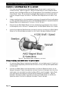
5. The Tractor Harness has a 3-pin Weather Pack connector labeled Ground Speed, either
an A328 Shaft/Speed Sensor Kit or A449 Radar Sensor Interface Harness (not included
in this kit) can be connected to this connector. Typically the Radar Sensor Interface
Harness would be connected to the Tractor Harness Ground Speed connector. Only
one (1) speed connector must be used at any one time. Refer to 1.2.2 for installing
the Shaft/Speed Sensor Kit or Radar Sensor Interface Harness.
Page 13
V1.98 21/06/06