


Major Topic Heading
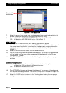
Setting Up- Flow
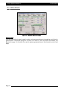
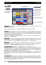
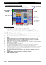
17.4 FLOW
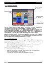
The ‘Volume Readout’ displays ‘Volume/Minute or ‘Volume/Nozzle, depending on which option
is selected from the ‘FLOW’ window.
There is a ‘Volume Readout’ displayed for each ‘Tank’ (1,2 and 3) selected. The above example
shows a ‘Volume readout’ for ‘Tank 1’ and ‘Tank 2’ because there are 2 tanks selected. The
number on the left hand side of the ‘Volume Readout’ displays which ‘Tank’ the ‘Volume
Readout’ is displaying.
The units displayed are determined by the units selected on the OPTIONS/UNITS page and
whether, ‘Liquid, Granular, Injection or NH3’ was selected for the ‘Tank Mode’.
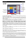
BByy
sseelleeccttiinngg
tthhee
‘‘VVoolluummee
RReeaaddoouutt’’
ddiissppllaayy;;
tthhee
‘‘FFLLOOWW’’
wwiinnddooww
iiss
ddiissppllaayyeedd
aas
s
sshhoowwnn
iinn
FFiigguurree
5577..
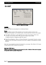
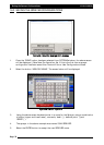
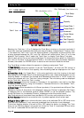
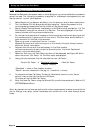
The current number of Nozzles is displayed. The number of nozzles can also be set from the
OPTIONS/SPRAYER page. To change the number of nozzles select the ‘Calculator Icon’; and enter
the number of nozzles for each boom section, for the primary boom. The number of nozzles does
not affect the operation of the sprayer. The number of nozzles is used to calculate an average
flowrate per nozzle. This is displayed in the ‘Volume Readout’ when the ‘Display Volume/Nozzles’
button is selected.
‘Display Volume/Minute’ is displayed in the ‘Volume Readout’ when ‘Display Volume/Minute’
button is selected from the ‘FLOW’ window.
‘Display Volume/Nozzles’ is displayed in the ‘Volume Readout’ when ‘Display Volume/Nozzles’
button is selected from the ‘FLOW’ window.
‘Range’ (Spray ECU 2 only)- shows the actual Pulse Width Modulation(PWM) applied to the
hydraulic valve as a percentage (%). Note: The ‘Range’ is only displayed for the ‘Tanks or Tank)’
which have ‘Proportional Valve’ selected as the Controller.
‘Time Left X’- Displays the approximate time left in (hh:mm) of spraying time before the tank is
empty; taking into account the current speed, volume left in tank, sections ON and widths and
application rate. The ‘X’ signifies which Tank (1,2 or 3) the Time Left is currently displayed. Each
Tank has its own Time Left display, the number of Time Left windows is determined by the
number of Tanks selected. ‘OFF’ is displayed where the time (hh:mm) is normally displayed, when
the Tank is switched OFF or the Master is switched OFF.
Page 84
V1.98 21/06/06
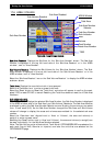
Volume Readout
for Tank 1
FLOW
Window
Nozzles
Display
Volume/ Minute
Range
Time
Display
Volume/ Nozzles
Volume Readout
for Tank 2
FFiigguurree
5577::
FFllooww
wwiinnddooww