


Major Topic Heading
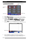
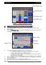
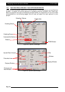
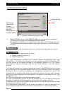
‘‘PPUUMMPP
iiss
OONN’’-
button only appears when ‘Spray ECU’, ‘Prop. Valve’ and ‘Enable Pump Control
Button’ are
aallll
selected. When selected the button says ‘PUMP is ON’ and turns ‘green’, this
switches the hydraulic pump ON. When selected again the button says ‘PUMP is OFF’ and
turns ‘red’, this switches the hydraulic pump OFF.
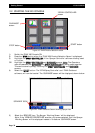
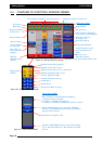
GGrroouunndd
SSppeeeedd-
Displays the actual ground speed whether from the wheel sensor on the
sprayer, tractor radar or GPS speed; depending what type was selected.
Selecting the ‘Ground Speed’ readout displays a ‘SPEED’ screen on the right hand side. See
Section 14.5 for details.
SSuubb
TToottaall
((AArreeaa))-
readout displays the area sprayed for the sub area selected depending on
the units selected. The number in the top left hand side of the readout, is displaying the
current sub area number. There are 10 sub area numbers (0 -9).
Selecting the ‘Sub Area’ readout displays an ‘AREA’ screen on the right hand side. See Section
14.6 for details.
SSuubb
TToottaall
((VVoolluummee
UUsseedd))-
readout displays the volume (or weight) sprayed for the sub area
selected depending on the units selected. The number in the top left hand side of the
readout, is displaying the current sub area number. There are 10 sub area numbers (0 -9).
Selecting the ‘Sub Area’ readout displays a ‘AREA’ screen on the right hand side. See Section
11.6 for details.
TTaannkk
IInnddiiccaattoorr-
Only appears when more than ‘1’ Tank is selected in OPTIONS/SPRAYER. This
allows the ‘Sub Total Area’ and ‘Sub Total Volume’ to be displayed for each tank. To change
which tank is displayed select either the ‘Sub Total Area’ readout or ‘Sub Total Volume’
readout, you will notice the ‘orange’ ‘Tank Indicator’ will change each time the readouts are
selected, this will then display the readouts for each tank.
PPuummpp
SSppeeeedd
RReeaaddoouutt-
This displays the actual pump speed. The Pump Speed readout is only
displayed if selected. See ‘Pump Options’ on the OPTIONS/ SETUP Page.
‘‘MMiinn..
FFllooww’’
oorr
‘‘MMiinn..
NNoozzzzllee
FFllooww’’
iinnddiiccaat
toorr-
A ‘red’ indicator will be displayed in the ‘Volume’
readout when the minimum flow for the regulator valve is reached or the minimum flow for
the nozzles has been reached. Select the ‘Volume’ readout to see the reason the red indicator
is being displayed. This will be displayed on the right hand ‘Flow’ window.
Getting Started
Overview of Functions- The ‘Working Screen’
Page 37
V1.98 21/06/06