


Installing the Spray ECU
1.1 INSTALLING THE SPRAY ECU (ALL MODELS)
Step
1:
Installing
the
Spray
ECU
30S
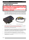
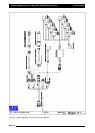
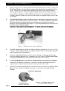
1. Mount the Spray ECU (Electronic Control Unit) shown in Figure 2 in a suitable position
inside the cab ensuring that it and its connectors cannot be accidentally damaged by
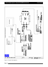
moving objects, the Spray ECU can be mounted in any orientation. Figure 4 shows the
in-cabin assembly showing Spray ECU, Switch Box, Power Comms and Tractor Harness.
Please refer to the ZYNX Console (X15 or X20) manual for mounting the ZYNX Console.
Page 11
V1.98 21/06/06
NNoottee::
DDIISSCCOONNNNEECCTT
TTHHEE
VVEEHHIICCLLEE
BBAATTTTEERRYY
bbeeffoorree
pprroocceeeeddiinngg
wwiitthh
aannyy
iinnssttaallllaattiioonn
oorr
sseerrvviicciinngg
ooff
tthhee
SSpprraayy
EECCUU
3300SS
oorr
TTrraaccttoorr
hhaarrnneessss..
BBeeffoorree
ccoommmmeenncciinngg
aannyy
i
innssttaallllaattiioonn
oorr
sseerrvviicciinngg
ooff
tthhee
SSpprraayyeerr
HHaarrnneessss
oorr
VVaallvvee
HHaarrnneessss,,
mmaakkee
ssuurree
tth
hee
TTrraaccttoorr
HHaarrnneessss
iiss
ddiissccoonnnneecctteedd
ffrroomm
tthhee
SSpprraayyeerr
hhaarrnneessss..
DDAAMMAAGGEE
WWIILLLL
OOCCCCUURR
iiff
aannyy
eexxtteerrnnaall
ppoowweerr
iiss
aapppplliieedd
ttoo
tthhee
SSeeccttiioonn
DDrriivvee
OOuuttppuuttss
oonn
tthhee
SSpprraayy
EECCUU..
AALLWWAAYYSS
DDIISSCCOONNNNEECCTT
TTHHEE
VVEEHHIICCLLEE
BBAATTTTEERRYY
bbeeffoorree
pprroocceeeeddiinngg
wwiitthh
aannyy
wweellddiinngg,,
j
juummpp
ssttaarrttiinngg
oorr
cchhaarrggiinngg
oonn
tthhee
vveehhiiccllee
oorr
sspprraayyeerr..
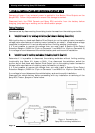
2. Install the Power/Comms Harness. Route the red and black wires to a 12 volt battery.
DO NOT CONNECT TO BATTERY, UNTIL INSTALLATION IS COMPLETE.
Use the cable ties provided to secure the Power/Comms Harness away from hot and
moving parts and to avoid chaffing and wear.
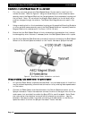
3. Plug the ‘Switched Power’ connector that is located on the Power/Comms Harness, into
the ‘Switched Power’ connector on the ZYNX Power Cable. If this connection is already
utilized, connect it via the A1953 Power Splitter Harness. This connection ensures that
the Spray ECU is only powered up when the ZYNX Console is switched ON.
4. One end of the Power/Comms Harness has 'DB 9-Pin' Comms Cable connection.
Connect this cable to the next available COM Port at the back of the ZYNX Console.
5. Connect the other end of the Power/Comms Harness to the 16-pin connector marked
‘POWER/COMMS’ on the Spray ECU.
Figure 2: Spray ECU 30S
Figure 3: Sprayer Switchbox