


Setup Options- Sections
SSeettttiinngg
nnuummbbeerr
ooff
sseeccttiioonnss
wwhheenn
uussiinngg
aa
pprriimmaarryy
sseeccttiioonn
vvaallvvee
ttoo
sswwiittcchh
sseeccoonnddaarryy
lliinnee
OONN
If the spray boom has been setup for example with 5 sections on the primary line and a section
valve to control the secondary line. Then select the ‘Lines’ as ‘Single’ and the number of
Sections as ‘6’
Then enter ‘5’ as the number of ‘Guidance Sections’.
Enter the section widths of each of the sections (1-5) and enter a zero width for the ‘6’ section.
Then see section 7.0 to set the ‘Low Speed Shutoffs’ for section ‘6’, set the ‘Low Speed Shutoff’
for section ‘6’ at the speed you require the secondary line to switch ON.
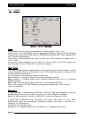
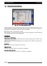
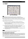
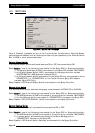
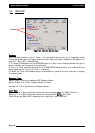
WWiiddtthhss-
To enter in the width for each boom section, touch the calculator pad next to
‘Widths’. Only the number of sections selected will be displayed. Each section has a calculator
pad next to it. Touch the calculator pad and enter in a value for each of the sections. If all the
sections are the same width then the ‘Set All’ button can be selected, enter in the section
width using the calculator keypad and select ‘Enter’, then all the sections will have that width
value entered. Select ‘OK’ to close the ‘Section Widths’ window when all section widths have
been entered.
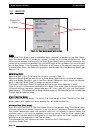
GGuuiiddaannccee
SSeeccttiioonnss
Enter in the number of section valves on the primary line. The Guidance sections are what are
displayed on the Guidance screen and are used to produce the coverage map.The Guidance
sections are also used by the ZYNX Guidance to know how many sections are used by the Auto
Section Control (ASC).
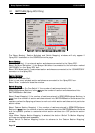
VVaallvveess
Hardi Sprayers require special hardware to operate. When fitting the ZYNX Sprayer controller
to an existing Hardi sprayer, the ZYNX needs to cater for their balanced valves. Balanced
valves, when closed, bypass the flow back to the tank instead of just stopping it. However, the
flow back to tank is being calculated by the ZYNX, therefore the system needs to know when
all the section valves are switched OFF; the signal pulses from the flow meter are ignored.
Select ‘Balanced’ when connecting the ZYNX system to a Hardi type sprayer with ‘Balanced’
valves.
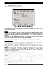
NNoozzzzlleess
TToottaall
The total number of nozzles fitted on the primary line can be entered here. This number is
used to calculate an average flowrate per nozzle which can be displayed on the ‘Working
Screen’. The number of nozzles is also used to calculate the ‘Min. Flow. The number of nozzles
should be the number of primary line nozzles only, with the nozzle count for each section
entered into the appropriate section.
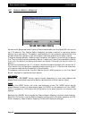
MMiinn..
FFllooww
The ‘Min. Flow’ allows a value to be entered which represents the minimum flow rate of the
nozzles fitted on the sprayer. This value can be found on the nozzle chart that came with the
sprayer. When this value is entered the spray controller will not allow the nozzle minimum
flow to fall below the value set. The spray controller will hold the regulator at that position
until the flow increases above the Min. Flow.
The Spray Controller knows what the total flow is, because of the feedback from the flow
meter; it knows how many sections are switched ON and how many nozzles are on each
section. Therefore it can determine the flow per nozzle. When the flow per nozzle falls below
the ‘Min. Flow Value’ a red indicator will appear on the Flow readout, on the ‘Working
Screen’
An explanation of the ‘red’ indicator’ can be seen by selecting the ‘Flow’ readout.
Page 59
V1.98 21/06/06