


Installation of Spray ECU 30S KEE Sprayer Kits
1.2.2 Installing
the
Sprayer
Harness
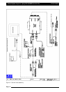
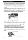
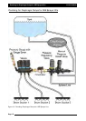
1. The Sprayer Harness connects to the Tractor Harness at the back of the tractor or
vehicle via the connector and continues across the sprayer's chassis to the valve
set. Figure 5 shows the Sprayer Harness and Valve Harness Assembly.
2. Do not cut or splice the Sprayer Harness. Excess cable should be strapped away to
avoid vibration and wear.The typical Sprayer Harness has 5 connectors, they are
labeled as follows:
GGrroouunndd
SSppeeeedd
- connects to the Shaft/Speed Sensor Kit which is supplied as part of this kit.
FFllooww
MMeetteerr
11
- connects to a flow meter (not supplied).
PPrreessssuurree
SSeennssoorr
11-
connects to the Pressure Sensor which is supplied as part of this kit.
RREEGG
VVaallvvee
11-
connects to a regulator valve (not supplied).
VVaallvvee
HHaarrnneessss-
connects to the Valve Harness which is supplied as part of this kit.
Note: The Sprayer Harness may have other connectors, refer to the Sprayer Installation kit that
came with your sprayer kit for more information. The Dump Valve connector may be located
on the Sprayer Harness. If the Valve Harness has an ‘Arag Interface box’ incorporated into the
Valve Harness, then the ‘Dump Valve’ connector will be located on the Valve Harness.
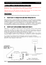
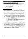
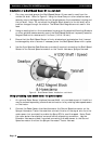
Troubleshooting Tip: For testing purposes on all 3-pin sensor connectors (Shaft/Speed Sensor
and Flow Meter) the voltage on each pin should be as follows: Pin A: +5 VDC Signal, Pin B:
Ground, Pin C: +12VDC Sensor Power. Refer to Figure 6 below:
Connecting
to
a
Speed
Sensor
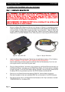
This installation is used if connecting an A328 Shaft/Speed Sensor Kit (for ground speed) or
A449 Radar Sensor Interface Harness (not supplied) to the Ground Speed connector on either
the Tractor Harness or Sprayer Harness.
CCoonnnneecctt
ttoo
oonnllyy
oonnee
((11))
ooff
tthhee
GGrroouunndd
SSppeeeedd
ccoonnnneeccttoorrss..
Select one of the following:
a) Installing the Shaft/Speed Sensor Kit to an un-driven wheel on either the Tractor
Harness or Sprayer Harness;
b) Installing the Shaft/Speed Sensor Kit to the Tail Shaft of a vehicle on either the Tractor
Harness or Sprayer Harness;
c) Use and existing radar speed sensor for ground speed.
Installation
of
the
Shaft/Speed
Sensor
kit
to
an
un-ddriven
wheel
for
Ground
Speed
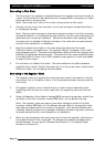
1. The Shaft/Speed Sensor and Wheel Stud Magnets can be fitted to any un-driven ground
wheel, for example: front wheel of tractor or wheel on trailing sprayer. The magnet
activates the sensor as the wheel magnets sweep past. Refer to Figure 8.
Note: Use of a driven wheel for ground speed may be subject to "wheel slip" and may
not always reflect true ground speed.
Page 16
V1.98 21/06/06
Figure 6 : 3-Pin Weather Pack Sensor