


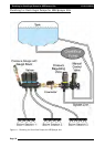

Installing Spray ECU 3 and Spray ECU 10SR
Digital
Multimeter
(DMM)
Test
Procedure
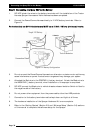
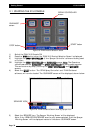
1. Testing voltage on section outputs on Raven Console Harness with switches on.
With DMM set to 20vdc insert Gnd probe into Gnd Pin (usually Pin 1) and Positive probe
into each section pin. Confirm yes or no to voltage present.
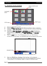
2. Testing for Gnd on section outputs on Raven Console Harness with switches off.
With the DMM set to ohms, insert Gnd probe into Gnd pin (usually Pin 1) and positive
probe into each section pin. Confirm yes or no to continuity.
Always disconnect the vehicle battery before proceeding with any installation or servicing of
the Spray ECU, Tractor, Sprayer or Valve Looms.
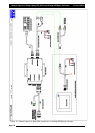
IInnssttaalllliinngg
tthhee
1100SSRR
SSpprraayy
EECCUU
1. Before removing the existing controller run the sprayer and record the minimum and
maximum pressure and flow rates attainable. Ensure that the system is functioning
correctly before removing the controller.
2. Record all of the calibration factors and section width values. These can then be easily
transferred to the ZYNX after installation.
3. Remove the controller.
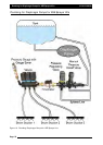
4. Refer to Section 1.1 for mounting the Spray ECU, Power/Comms Harness and Sprayer
switchbox
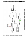
5. Connect the existing Raven Console harness to CONNECTOR 1 or 3 of the Spray ECU.
6. Connect existing Raven Gnd/Radar speed input to the ‘SPEED’ connector on the Spray
ECU.
7. Carefully run the power lead to the tractors battery ensuring it is tied away from
moving, hot or sharp objects.
8. To complete the installation go to Section 1.5 to connect the Spray ECU Power/Comms
harness to the battery.
Page 28
V1.98 21/06/06