


Setup Options -Sensors
9.0 SENSORS
FFLLOOWW
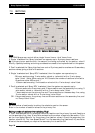
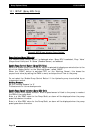
Note: Most Flow Sensors have a calibration factor stamped or labeled on the Flow Sensor
body.The factor will be in ‘pulses per volume’, (volume can be Litres, US Gallons etc). This
factor may be entered manually into the ‘Flow Sensor Specifications’ window. Make sure the
correct units (volume) are selected from the UNITS page, which correspond to the units used
on the Flow Sensor. If the Flowmeter Calibration is not known or the operator wants to check
the Calibration Factor, the Calibration procedure must be used from the ‘Working Screen’, see
Section 17.8.
CCaalliibbrraattiioonn
FFaaccttoorr
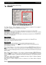
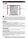
Select the Tank (1,2 or 3) the using the ‘Arrows’, (normally ‘Tank 1’).
Select the ‘Sensor Specifications’ button, a ‘Flow Sensor Specifications’ window will appear.
Using the Screen Calculator type in the Flow Sensor Calibration, don’t forget the decimal
point if required. Select ‘Enter’ to accept and save the factor.
The current ‘Calibration Factor’ is displayed and the current units displayed in ‘blue’.
Note: If typing in a Flow sensor calibration for a Raven Flow sensor then divide the factor by
10 before entering the factor, (Raven label says ‘187’; then type ‘18.7’ into the ‘Flow Sensor
Specifications’). This is because the Raven console does not have decimal points and assumes
the last digit is a decimal place.
MMiiccrroo-TTrraakk
FFllooww
SSeennssoorr
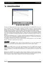
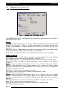
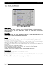
Select ‘Micro-Trak Flow Sensor’ if a ‘Micro-Trak’ flow sensor is fitted. The Micro-Trak Flow
sensor uses a ‘latch’ system and when enabled the software handles this.
MMiinniimmuumm
FFllooww
((FFllooww
MMeetteerr))
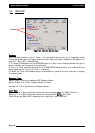
Enter the ‘minimum flow’ of the Flow Meter fitted to the sprayer. Every Flow Meter has a
minimum value which below this point, it can not control accurately. Therefore when the
Flow Meter reaches this value, the regulator valve will not attempt to control below this
minimum value, it will hold the regulator valve at that point. Then the ‘Flow’ readout will
display a red indicator alerting the operator of this. Then select the ‘Flow’ readout and an
explanation will be displayed in the Flow window.
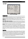
This is because the ‘red’ indicator can mean ‘Minimum Flow’ (Flow Meter) or
‘Minimum Nozzle Flow’.
Page 65
V1.98 21/06/06
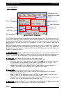
Calculator Icon
Units used
Current Cal
Factor
FFiigguurree
4400::
FFllooww
SSeennssoorr
ssppeecciiffiiccaattiioonnss
ppaaggee