


1.4 REPLACING
EXISTING
RAVEN
CONTROLLER
WITH
A
SPRAY
ECU
10SR
OVERVIEW
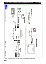
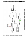
The 10SR Spray ECU have been pinned to allow direct replacement of some of the Raven 4xx,
6xx, 4400 and 4600 series controllers.
Generally most 4xx, 6xx and 4400 series controllers with inbuilt section switches can be
replaced with no need for adaptors. Connector 1 is used for the 4400 series, Connector 2 for
4600 series and connector 3 for the 4xx and 6xx series controllers.
Direct PWM control is not possible with direct connection to the Spray ECU. Adaptor looms
will be required.
It is important to note that
nnoott
all Raven 37 and 16-pin connectors are pinned alike. Subtle
differences do occur in some looms so it is extremely important to confirm the pin locations
and functions are the same as the Spray ECU before connection as damage can occur. Locate
the Raven console harness part number (E.g.115-0159-xxx) and use the relevant Raven console
harness wiring diagram to help confirm the pin locations. If the pins and functionality are not
the same as the ECU do not connect to it. Contact your KEE dealer and confirm if an adaptor
for this application is available.
Note: that damage will occur if any external power is applied to the section drive outputs on
the Sprayer ECU. Follow this procedure before installing the ECU to ensure that damage is
avoided.
SWITCHES
ON
EXISTING
CONTROLLER
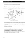
1. With ignition key on, check each section drive output pin on the existing Raven
console harness for voltage (use DMM test procedure below). Locate where
voltage is supplied from to determine if it can be removed without limiting
existing functionality.
2. If it is not possible to remove this voltage then you must install a Section Drive
Output Protection Adaptor.
(A2812 for 37-pin on Connector 1 and A2813 for 16-pin on Connector 3)
ANY
EXTERNAL
SWITCHES
SEPARATE
TO
EXISTING
CONTROLLER
(E.g. Joystick and dash board switches)
Replacing 4xx, 6xx, 4400 and 4600 controllers that use external section switches is possible
however the following steps MUST first be confirmed prior to installing of the ECU.
1. Determine if it is possible to disconnect the existing switchbox without limiting
existing functionality (e.g. Boom Lift, Lower or Fold).
2. If yes, disconnect the switchbox, switch the ignition key on and check each Section
Drive Output pin on the existing Raven console harness for voltage. If no voltage is
present continue with installation.
3. If no, and voltage is present and cannot be removed then you must install a Section
Drive Output Protection Adaptor between the ECU and the existing tractor harness.
(A2812 for 37-pin on Connector 1 and A2813 for 16-pin on Connector 3)
4. With all of the section switches in the off position confirm that each section pin on the
Raven harness does NOT have continuity to Gnd. If Gnd exists on any of these pins with
the section switches in the off position, and the switchbox cannot be disconnected. DO
NOT proceed with installation.
5. If external switches must remain connected they must always be switched to the OFF
position or ASC will not function correctly.
Installing Spray ECU 3 and Spray ECU 10SR
Page 27
V1.98 21/06/06