


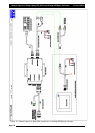

Installation of Spray ECU 30S KEE Sprayer Kits
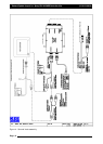
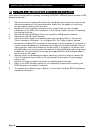
9. Once all the ARAG connectors are in place, using a screwdriver tighten the screw at the
top of the ARAG connector to secure the connector to the section and dump valves.
10. Tidy any excess harness using cable ties.
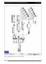
11. To complete the installation go to Section 1.5 to connect the Spray ECU Power/Comms
harness to the battery.
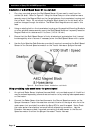
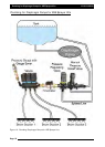
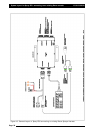
Explanation
of
the
Different
types
of
Valves
22-wwiirree
VVaallvvee
((RReevveerrssee
PPoollaarriittyy))
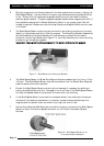
Refers to an electric section, dump or regulator valve. The valve is driven by an electric motor
that is able to rotate in both directions. 2 wires are connected to this type of valve from the
controller. To rotate the motor 12v is applied to one of the wires whilst GND is applied to the
other. When opposite voltage is applied to the two wires the motor will rotate in the opposite
direction. Common terms for this system are Reverse Polarity or Bi-Directional.
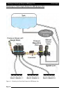
33-wwiirree
VVaallvvee
Refers to an electric section, dump or regulator valve. The valve is driven by an electric motor
that is able to rotate in both directions. Unlike the 2-wire valve, the 3-wire valve has inbuilt
changeover relays that change the motor direction depending on whether 12v or 0v is applied
to the signal wire.
Constant 12v and GND are required in addition to the signal wire.
SSoolleennooiidd
VVaallvvee
Refers to electromagnetic coil type valves. They usually consist of a coil that when exposed to
voltage produces a magnetic field. The magnetic field draws a needle against a spring away
from it’s seat to allow liquid to flow.
GND and 12v signal is required for this type of valve.
Page 22
V1.98 21/06/06