


Getting Started
Overview of Functions- The ‘Working Screen’
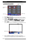
BBoooomm
SSeeccttiioonnss-
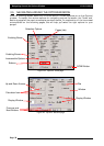
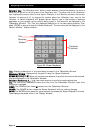
Displays the number of boom sections selected. A ‘Dual’ boom is shown,
showing the front and back lines; the top line representing the front line and the bottom line
displaying the back line. If ‘Single’ line is selected in OPTIONS/SPRAYER then only a single line
of sections would be displayed. The boom sections are numbered starting from the left hand
side of the spray line with the far left section valve being section valve ‘1’.
The boom sections can be switched ON/OFF either by touching the boom section on the
‘Working Screen’ or switching the boom sections switches ON/OFF on the ‘External Switch
Box’.
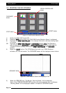
SSpprraayyiinngg
IInnddiiccaattoorrss-
are displayed below the boom sections. On the ‘Working screen’
displayed on Page 9 there are 16 ‘Spraying Indicators’, because there are in total 16 section
valves (8 front section valves and 8 back section valves). The first eight ‘Spraying Indicators’ on
the left represent the boom sections on the front line, the next eight, on the right represents
the boom sections on the back line.
When a ‘Spraying Indicator’ is ‘grey’ means the boom section is NOT spraying.
When a ‘Spraying Indicator’ is ‘green’ means the boom section IS spraying.
When the boom sections are ‘grey’ in colour indicates the sections are switched OFF.
When the boom sections are ‘red’ in colour indicates the sections are switched ON but the
‘Low Speed Shutoff’ speed has not been reached.
When the boom sections are ‘green’ in colour indicates the boom section is switched ON, the
‘Low Speed Shutoff’ has been achieved and ready to start spraying.
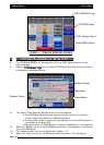
When a boom section is ‘green’ and ‘Spraying Indicator’ is ‘grey’ indicates the boom section is
ready for spraying but the ‘Master’ is OFF.
When the ‘Master’ is switched ON, boom section is ‘green’ and ‘Spraying Indicator’ is ‘green’
then the boom section valve is spraying.
When using the Automatic Section Control (ASC) when the sections are switched OFF, under
ASC the boom sections turn ‘grey’ and the ‘Spray Indicators’ turn ‘grey’; when switched ON
under ASC both the boom sections and ‘Spray Indicators’ turn ‘green’.
AAUUTTOO-
button when selected (by selecting ‘Auto’ on the switch box or selecting the ‘AUTO’
button from the ‘Working Screen’), will become highlighted and a green indicator will be
shown on the ‘AUTO’ button. When ‘AUTO’ is selected the ZYNX Spray Controller is
automatically adjusting the flow according to speed and area.
MMAANNUUAALL-
button when selected (by selecting ‘Manual’ on the switch box or selecting the
‘MANUAL’ button from the ‘Working Screen’), will become highlighted and a green indicator
will be shown on the ‘MANUAL’ button.
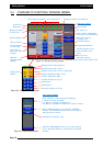
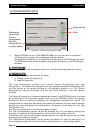
SSyysstteemm
PPrreessssuurree-
displays the system pressure if an electronic pressure sensor is installed and
selected in the OPTIONS/SPRAYER. The number in the top left hand corner indicates which
tank (1,2 or 3) the system pressure reading is from.
Selecting the ‘System Pressure’ button displays a ‘TANK PRESSURE’ screen on the right hand
side. See Section 14.1 for details.
VVoolluummee
RReeaad
doouutt-
displays Volume per minute (for the front line) or Volume per nozzle (for
the front line nozzles), depending which was selected.
Selecting the ‘Volume Readout’ button displays a ‘FLOW’ screen on the right hand side. See
Section 14.4 for details.
Page 36
V1.98 21/06/06