


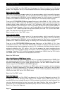

Setup Options -Tanks
To set the ‘Max PWM’ and ‘Min PWM’ put the sprayer into ‘Manual’ mode from the ‘Working
screen’, with Agitation on Full, All boom sections ON and a manual pressure gauge installed.
SSeettttiinngg
tthhee
‘‘MMaaxx
PPWWMM’’
Determine the maximum pressure value for the spraying system, which is normally the upper
limit of the nozzles being used . For this example we will use 500kpa. From the ‘Working
Screen’, making sure the ‘MANUAL’ button is selected; select the ‘Inc’ buttons to increase the
pressure until 500kPa is reached, taking the reading from the manual pressure gauge.
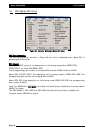
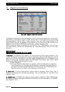
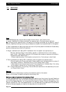
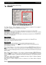
Then go to OPTIONS/SPRAYER/Settings page. Starting at a ‘Max PWM’ of ‘FULL’ (100%), then
drop the value to ‘95%’, select the ‘OK’ button to accept the change; then take a look at the
pressure gauge. Keep dropping the value in 5% increments, after each change, close the
window by selecting the ‘OK’ button. Until the pressure just starts dropping below 500kPa on
the manual pressure gauge; at this point, use the value before the pressure started dropping.
Therefore if ‘70%’ made the pressure drop below 500kPa, then use ‘75%’ as the ‘Max PWM’
value. The value will normally be around 75%.
Select a value for the ‘Max PWM’ value.
SSeettttiinngg
tthhee
‘‘MMiinn
PPWWMM’’
Determine the minimum pressure value for the spraying system, which is normally the lower
limit of the nozzles being used . For this example we will use 100kpa. From the ‘Working
Screen’, making sure the ‘MANUAL’ button is selected; select the ‘Dec’ button to decrease the
pressure until 100kPa is reached, taking the reading from the manual pressure gauge.
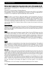
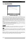
Then go to the OPTIONS/SPRAYER/Settings page. Starting at a ‘Min PWM’ of ‘5%’, then
increase the value to ‘10%’, select the ‘OK’ button to accept the change; then take a look at
the pressure gauge. Keep increasing the value in 5% increments, after each change, close the
window by selecting the ‘OK’ button. Until the the pressure just starts increasing above
100kPa on the manual pressure gauge; at this point, use the value before the pressure started
increasing. Therefore if ‘30%’ made the pressure increase above 100kPa, then use ‘25%’ as the
‘Min PWM’ value. The value will normally be around ‘25%’.
Select the ‘PWM value’
UUssiinngg
‘‘HHiigghh
MMiinniimmuumm
PPWWMM
RRaannggee’’
ooppttiioonn
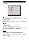
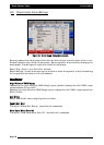
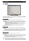
Note: If after selecting 40%PWM and there is still no increase of pressure above 100kPa, then
your system may have a Minimum PWM value above 40%. If this is the case then select ‘High
Minimum PWM Range’ from the ‘Valve Options’ window. The ‘Min PWM’ window will now
have a range from 42.5%PWM to 60%PWM displayed.
Continue the procedure of increasing the PWM value until the pressure starts increasing
above the 100kPa as displayed by the manual pressure gauge at this point, use the value
before the pressure started increasing. Therefore if ‘47.5%’ made the pressure increase above
100kPa, then use ‘45%’ as the ‘Min PWM’ value
Select the ‘Min PWM’ value.
CCoonnttrroolllleerr
RReessppoonnssee
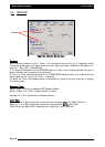
Once the ‘Max PWM’ and ‘Min PWM’ have been set, the ‘Controller Response’ can be set. Put
the spray into ‘AUTO’ spraying mode. Start at the ‘Fastest’ option, select a spray rate for
example 80L/ha then increase the rate to 100L/ha and see how quickly the rate changes. If the
rate over shoots and starts ‘hunting’ too much then select ‘Medium Fast’ option. Repeat the
procedure until the rate selected is obtained quickly without over shooting too much.
Select the ‘Controller Response’.
Page 57
V1.98 21/06/06