


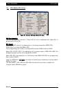

Software Setup Options-ECU
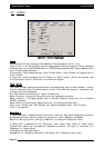
5.0 ECU (Electronic Control Unit)
Controller
Note: See Section 20 to select the correct controller, if unsure.
Select ‘Spray Interface’ if one of the following is written on the spray controller:
1- KEE Sprayrate Interface
2- ZYNX 5500 Interface
3- ZYNX 2500 Interface OR
Select ‘Spray ECU’ if ‘SPRAY ECU’ is written on the Spray Controller.
Select the correct controller.
If ‘Spray ECU’ has been selected then see extra pages, after the following sections;
ECU, Tanks, Switches and Sensors. Extra windows will become available, which
become visible after ‘Spray ECU’ is selected as the controller.
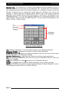
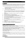
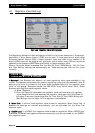
Com
Port
Select which Communications Port (Com Port) the 9 pin serial cable from the ‘Spray Controller’
is connected to the back of the ZYNX Console. Usually Com Port 2 is selected. Com Port 1 is
usually reserved for the ZYNX Guidance GPS or DGPS receiver.
If the Com Port is changed or selected for the first time the ZYNX Spray Controller software
will have to be restarted.
Simulation is selected for desktop use when the ZYNX Console is not connected to the Spray
ECU. This disables all the alarms.
The Com Ports are greyed out if the ZYNX Spray Rate software is not registered, contact KEE
to register. See Section 2.1
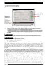
Using
Injection
ECU
To select this option an additional ‘Chemical Injection’ pump would have to be
purchased, an additional ‘Multi Drive Electronic Control Unit’ (MDECU) and looms
would also be required. This option with the appropriate hardware will allow all the
‘Spray ECU’s’ to control up to 3 injection tanks if connected to a 4 channel MDECU.
Otherwise leave unselected.
A Supplement Manual will be required to install the ‘Chemical Injection Pump’.
Page 48
V1.98 21/06/06
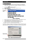
FFiigguurree
2299::
OOppttiioonnss-
EECCUU
ppaaggee