


STE 58760
- -
1-21
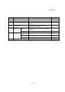
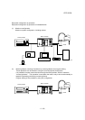
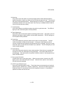
1.6 NAMES AND FUNCTIONS OF SR7000 CONTROLLER
The start up operation is conducted using the control panel and teach pendant. The external
views of the control panel and teach pendant are shown in Figures 1.5 and 1.6.
1.6.1 Control Panel
The control panel is used to turn on and off the power and perform automatic operation. This
paragraph outlines names and functions of the controls. The numbers referenced accord with
those in Figure 1.5.
1. Main power switch:
Power switch for the controller.
2. Circuit protector:
Circuit protector for the controller control circuit.
3. J1 connector:
Connector for communication channel 1.
4. J2 connector:
Connector for communication channel 2.
5. TP connector:
Connector for connecting the teach pendant.
6. FDD connector:
Connector for floppy disk drive unit(optional).
7. EMERGENCY switch:
Switch which unconditionally stops the robot operation. When this switch is pressed, the
servo power is turned off and an emergency stop state signal is output. Once this switch
is pressed, it is locked in the pressed position. To unlock this switch, turn the switch in the
direction of the arrow.
8. SERVO POWER OFF switch:
A switch which turns off the servo power to stop robot operation. When the servo power is
turned off, the lamp on the "OFF" switch lights.