


STE 58760
- -
2-19
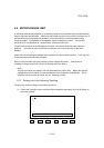
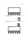
Repeat this key operation until the "JLIMIT>" command appears on the LCD display.
NEXT
F6
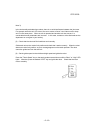
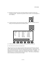
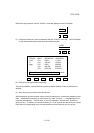
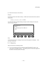
(3) Press the function key which corresponds with the "JLIMIT>" command. The LCD display
on the teach pendant should then show the following screen.
JLIMIT
F4
TRAVEL JOINT <NEGATIVE> <POSITIVE>
[mm] <T1> -5.868 111.000
or <T2> -138.000 138.000
[deg] <T3> -0.500 200.500
<T4> -400.000 400.000
<T5> -5729.578 5729.578
> _
N1-mem P1-mem N2-mem P2-mem N3-mem <next>
F1 F2 F3 F4 F5 F6
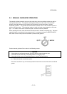
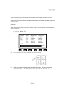
(4) Enter joint limit values with numeric keys.
The joint limit position value of the axis to be set should be entered in units of millimeters or
degrees.
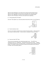
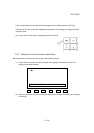
(5) Store the joint limit position value of each axis.
After entering the joint limit position values, press the function key on the teach pendant to store
them. Above the function keys, a menu having "P1-mem"
"N1-mem ...". corresponding to the
controller axes appears. The first letter "P" and "N" represent + direction and - direction of
each joint axis. In addition, the number following "P" or "N" accords with the robot joint number.
Press the key corresponding to the axis and direction for which the joint limit is to be set.