


STE 58760
- -
1-22
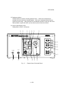
9. SERVO POWER ON switch:
A switch which turns on the servo power. When the servo power is turned on, the lamp on
the "ON" switch lights and a servo ON state signal is output. Unless the servo power is
turned on, the robot cannot be operated.
10. STOP switch:
A switch which stops automatic operation. When this switch is pressed in the automatic
operation mode, the lamp on the "STOP" switch lights and the robot stops automatic
operation after it completes the current operation. When the robot stops, the "START"
switch lamp turns off.
11. START switch:
A switch which starts automatic operation. When the robot starts automatic operation, the
lamp on the "START"
switch lights.
12. CYCLE STOP switch:
A switch which selects the mode that performs one cycle of automatic operation. This
operation mode is called the cycle operation mode. In the cycle operation mode,
automatic operation stops after the robot has executed the program. When the cycle
operation mode is selected, the lamp on the "CYCLE STOP" switch lights.
13. PC connector:
Connector for connecting a personal computer substituting for a floppy disk unit.
14. MASTER MODE KEY switch:
A key switch which selects one of robot modes; external automatic mode (EXT), internal
automatic mode (INT), and manual mode (MANU). The modes selected with this switch
are called master modes.
15. POWER LED:
Power lamp for the controller. When the main power is turned on, the "POWER" lamp
lights.
16. FAULT LED:
Error lamp for the controller. When a fault is detected, the "FAULT" lamp blinks.
17. Buzzer:
When a fault is detected, the buzzer beeps. When the STOP switch is pressed, the buzzer
stops beeping.