


12-5
A2677 Rev 1.5
X20 Sprayer Reference Manual
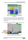
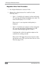
State 2• —Controller set to manual, sections and master
ON, pressing and holding the decrease arrow (▼).
The meter should display opposite to State 1.
Confirming this verifies the regulator outputs on the
controller are working correctly.
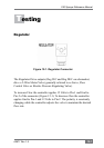
Please note: If the Dump valve opens when it should
close swap the wires connected to Pin-1 and Pin-2 in
the connector (Figure 12-3 on page 12-4).
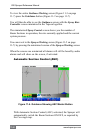
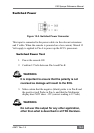
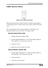
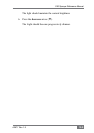
Topcon Sensors
All shaft sensor inputs (other references Flow Sensor, Speed Sensor,
Encoder and Feedback) are pinned alike.
Each time the Sensor is exposed to magnetic field (Hall effect) or
metallic objects (Proximity) the circuit is closed between Pin-A and
Pin-B. The controller sees this as 0 Volts, then 5 Volts when the sensor
is clear of the magnet or metallic object.
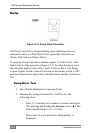
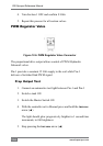
Sensor Input Test
Power ECU on 1.
On the Harness with the sensor disconnected check: 2.
• 11-12 Volts between Pin-B and Pin-C
Figure 12-4. Sensor Connector