


Return to Section TOC Return to Section TOC Return to Section TOC Return to Section TOC
Return to Master TOC Return to Master TOC Return to Master TOC Return to Master TOC
TROUBLESHOOTING & REPAIR
F-50 F-50
COMMANDER 400
CHARGING CIRCUIT TEST (continued)
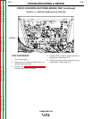
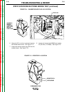
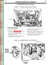
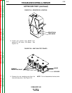
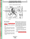
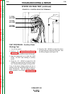
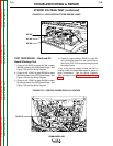
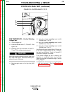
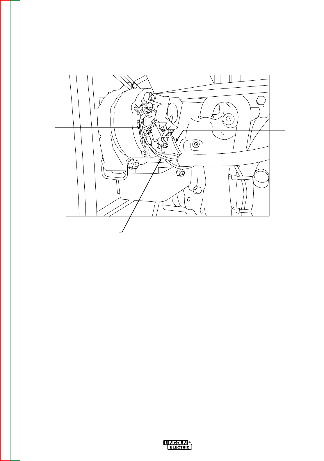
FIGURE F.22 – ENGINE ALTERNATOR LOCATION
#239
#238
#285(#281)
TEST PROCEDURE
1. Turn the engine off.
2. Perform the Case Cover Removal
Procedure up to Step 7.
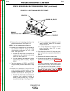
3. Locate the engine alternator. See Figure F.22.
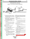
4. Start the engine and run it at high idle (1900
RPM).
5. Set the voltmeter for DC volts and measure
the DC volts at lead #239 to engine ground.
See the Wiring Diagram. Normal is 12.5 to
14.5VDC.
6. Set the voltmeter for DC volts and measure
the DC volts at lead #238 to engine ground.
See the Wiring Diagram. Normal is 12.5 to
14.5VDC.
7. Set the voltmeter for DC volts and measure
the DC volts at lead #285 to engine ground.
See the Wiring Diagram. Normal is 12.5 to
14.5 VDC.
NOTE: Some earlier machines may have a lead
#281 instead of #285. Lead #285 carries the
flashing voltage for the engine alternator. Battery
voltage should be present whenever the engine is
running. See the Wiring Diagram. On the earlier
machines, lead #281 carries the flashing voltage
for the engine alternator. Battery voltage should
be present whenever the start button (S2) is
pushed. See the Wiring Diagram.
8. If the correct flashing voltage is present and
the charging output voltage is low or missing,
the engine alternator may be faulty.
9. Stop the engine and check alternator V-belt
for proper tension. See the engine operation
manual.
10. Replace all case covers that were removed.
(See the Case Cover Removal Procedure.)