TROUBLESHOOTING & REPAIR
F-93 F-93
COMMANDER 400
Return to Section TOC Return to Section TOC Return to Section TOC Return to Section TOC
Return to Master TOC Return to Master TOC Return to Master TOC Return to Master TOC
SCR/DIODE RECTIFIER BRIDGE
REMOVAL AND REPLACEMENT (continued)
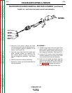
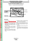
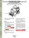
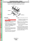
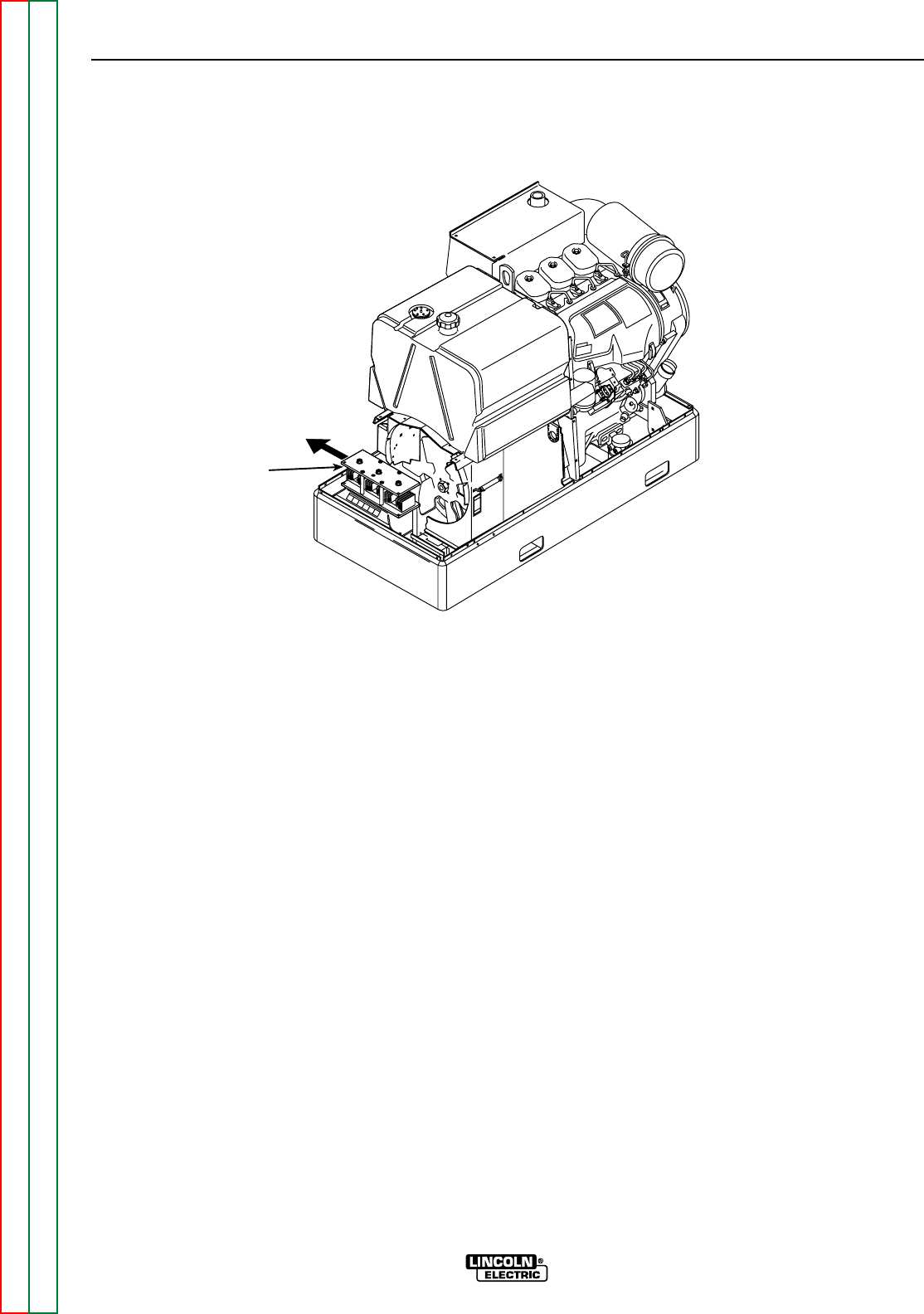
FIGURE F.42 – SCR/DIODE RECTIFIER BRIDGE ASSEMBLY REMOVAL
RECTIFIER
15. Carefully lift and slide the SCR/diode rectifier
bridge assembly out the left side of the
machine. See Figure F.42.
REASSEMBLY
16. Carefully lift and slide the SCR/diode rectifier
bridge assembly into the machine from the
left side. See Figure F.42.
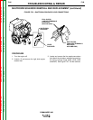
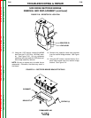
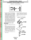
17. Using the 3/8" wrench, install the four (2 on
each side) screws holding the SCR/diode
rectifier bridge assembly rectifier bridge
bracket. See Figure F.41.
18. Attach the capacitor leads and grommet to
the rectifier bridge bracket. See Figure F.41.
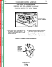
19. Using the 11/32" wrench, attach the #204B
lead to the R1 (50 Ohm -100 Watt) resistor.
See Figure F.40.
NOTE: Be sure to replace any cable ties cut dur-
ing removal. Otherwise, the leads may catch in
the blower.
20. Connect plug J30 to the snubber board.
Install the snubber board cover using the 3/8"
wrench.
21. Using the 3/4" wrench, attach lead #207 to
the negative "stick" output terminal. Replace
any cable ties cut during removal.
22. Feed plug J6 and the toroid assembly into
the control box. Connect plug J6 to the con-
trol board. Replace any cable ties cut during
removal. Using the 5/16" nut driver, install
the control board cover.
23. Using the 1/2" wrench, attach the shunt to
the positive heat sink plate (lower). Attach
the heavy #204C lead from the positive heat
sink plate (lower). Attach lead #209 (small)
and #209A (large) to the negative (upper)
heat sink plate. Attach the stator weld wind-
ing leads to the SCR/diode rectifier bridge
assembly. Replace any cable ties cut during
removal.
24. Replace the front shroud and all case covers
that were removed. (See the Case Cover
Removal and Replacement Procedure.)


