


TROUBLESHOOTING & REPAIR
F-83 F-83
COMMANDER 400
Return to Section TOC Return to Section TOC Return to Section TOC Return to Section TOC
Return to Master TOC Return to Master TOC Return to Master TOC Return to Master TOC
CONTROL PC BOARD REMOVAL AND REPLACEMENT (continued)
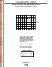
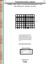
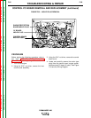
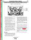
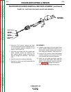
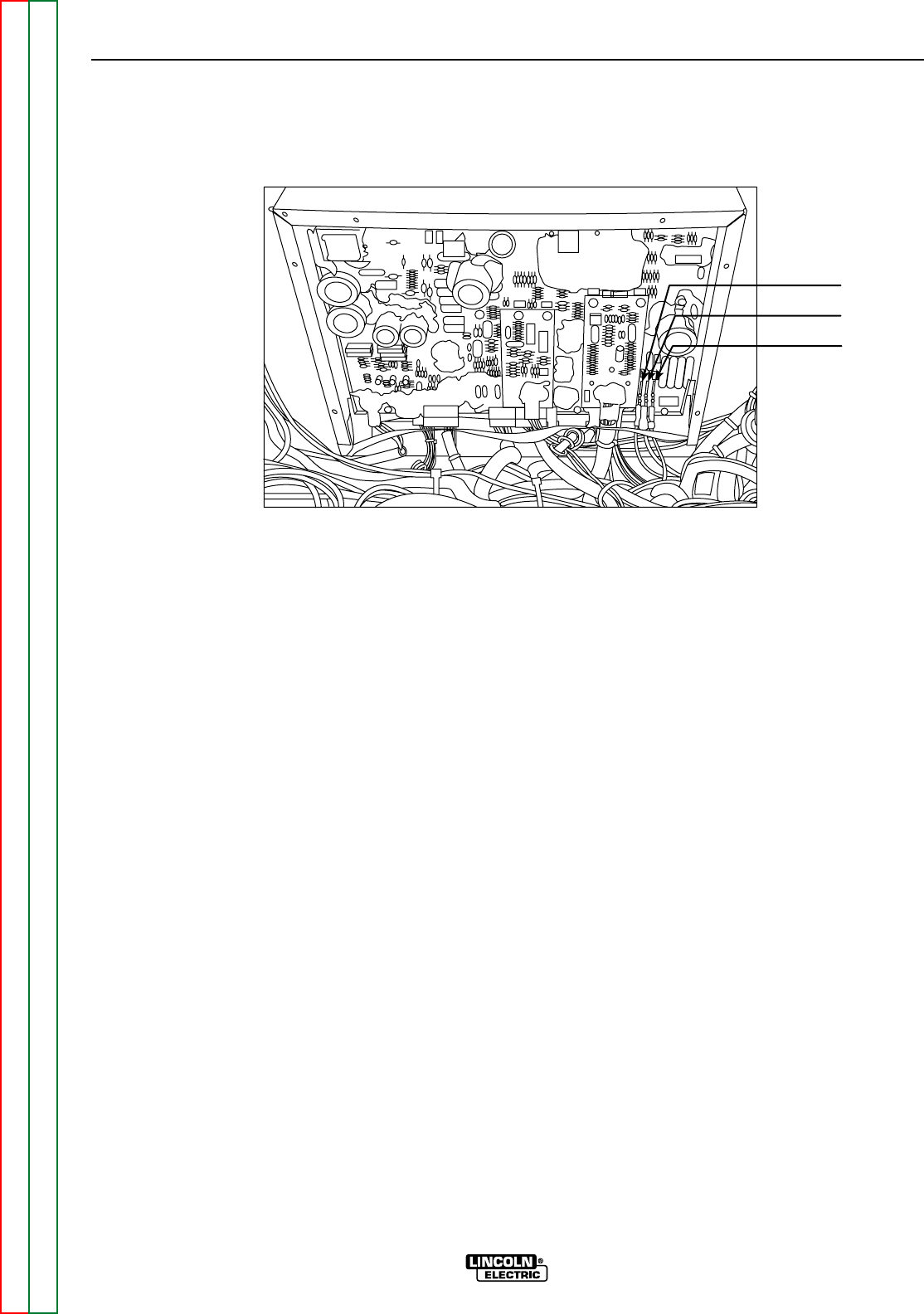
FIGURE F.34 – CONTROL BOARD LEADS
P e l 9 9 6
B1/227
B2/262
B3/232
5. Remove lead #227 from terminal B1 on the
control board. See Figure F. 34.
6. Remove lead # 262 from terminal B2 on the
control board. See Figure F.34.
7. Remove lead #232 from terminal B3 on the
control board. See Figure F.34.
8. Note lead placement and routing through
insulation for reassembly.
9. Using the phillips head screw driver, remove
the control board mounting screws. Note the
location of the different types of screws for
reassembly. The machine screws have lock
washers and flat washers, and they mount
the board to welded nuts. The sheet metal
screws mount to the nylon standoffs.
10. Carefully remove the control board assembly.
Note insulation placement for reassembly.
11. Using the phillips head screw driver, careful-
ly remove the engine protection board and
CV board (if used).
REASSEMBLY
12. Using the phillips head screw driver, careful-
ly assemble the engine protection board and
CV board (if used) to the new control board.
13. Carefully fit the control board assembly in
place. Note insulation placement.
14. Using the phillips head screw driver, mount
the control board with the appropriate mount-
ing screws. The machine screws have lock
washers and flat washers, and they mount
the board to welded nuts. Make sure these
are secure since they are used to ground the
control board. The sheet metal screws
mount to the nylon standoffs.
15. Attach the leads to the control board. Note
lead placement and routing through insula-
tion.
Lead #227 to terminal B1. See Figure F. 34.
Lead # 262 to terminal B2. See Figure F.34.
Lead #232 to terminal B3. See Figure F.34.
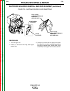
16. Carefully connect the molex type plugs to the
control board, engine protection board and
CV board (if used). See Figure F.33 and the
Wiring Diagram.
17. Using the 5/16" nut driver, install the control
board cover and the front control cover
assembly.
18. Perform the following calibration procedure.