


TROUBLESHOOTING AND REPAIR
FINE CONTROL POTENTIOMETER TEST (continued)
F-56 F-56
Return to Section TOC Return to Section TOC Return to Section TOC Return to Section TOC
Return to Master TOC Return to Master TOC Return to Master TOC Return to Master TOC
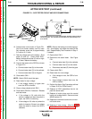
TEST PROCEDURE
NOTE: In this test procedure, the positive output
stud is used for common.
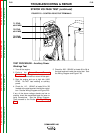
1. Using the 5/16” nut driver, open the control panel
and tilt out. Remove the control board cover.
Put the LOCAL/REMOTE switch in the “LOCAL”
position. Set the range switch to the general fab-
rication tap. Start the machine.
There are high voltages present
inside the control box while the
machine is running. THE VOLTAGES
ARE HIGH ENOUGH TO KILL. Use
extreme caution to avoid the back-
side of the receptacles, breakers, and
terminal strip while checking voltages inside the
control box.
2. With the control potentiometer in the minimum
position, check the voltage at the control board
from J8 pin 8 to common. Voltage should be
approximately -.025 VDC.
3. Slowly turn the control potentiometer CW. The
voltage should steadily increase from approxi-
mately -.025 VDC in the minimum position to
approximately 5.00 VDC in the maximum posi-
tion. Also, the display on the control panel
should steadily increase from 50-575.
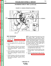
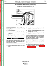
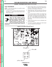
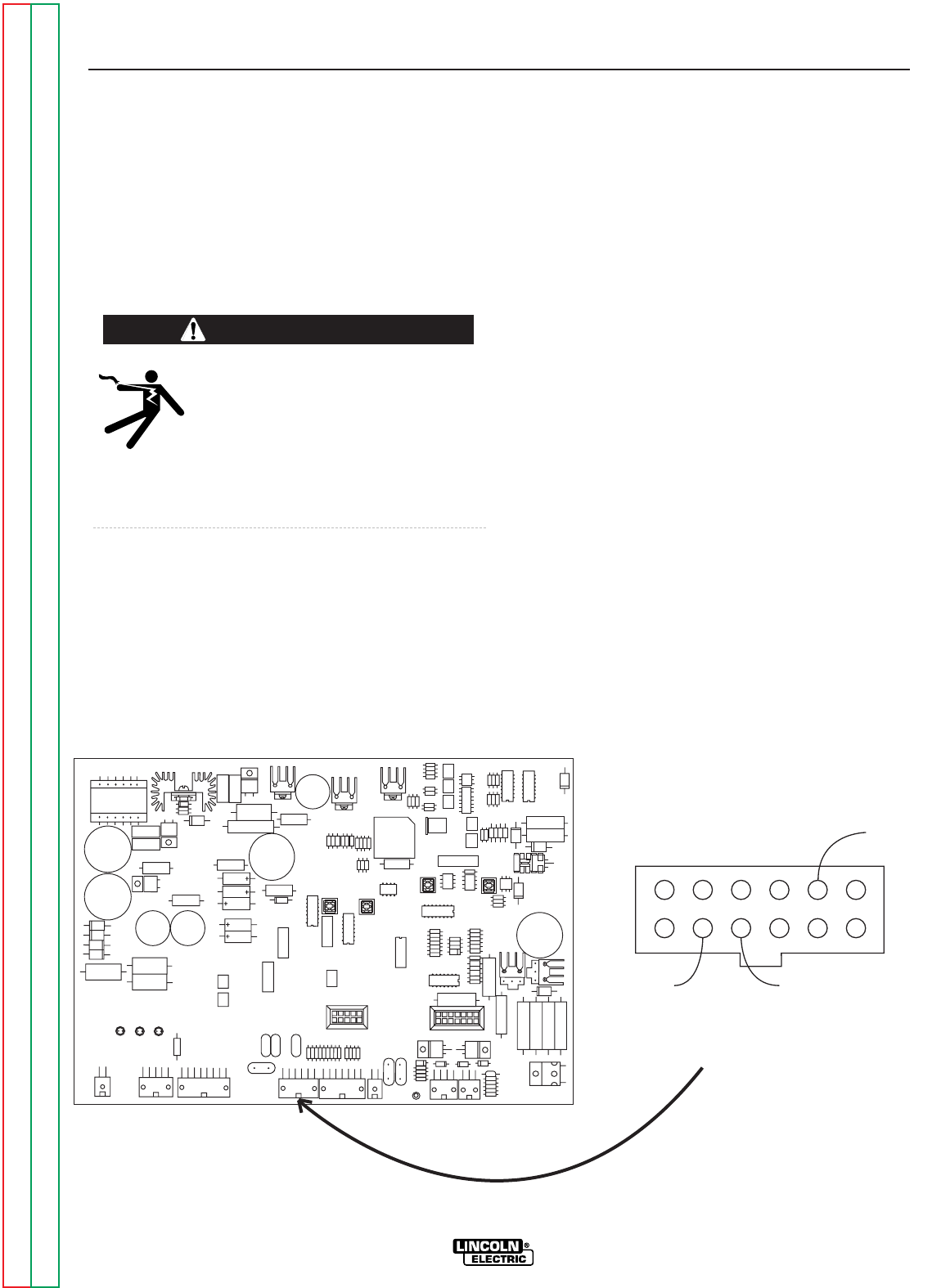
4. If step 2 or 3 fails, turn off the machine. At J8
pins 5,8, & 9, perform a resistance check of the
fine control potentiometer (the control poten-
tiometer is a 10K ohm potentiometer). See
Figure F.27. Also, check continuity of all fine con-
trol potentiometer leads and LOCAL/REMOTE
switch. If any of the leads, switch or poten-
tiometer fails the resistance check, replace the
faulty component.
5. If the leads, switch and potentiometer pass the
resistance check, disconnect the J8 from the
control board and start the machine. Check the
voltage from J8 pin 9 to common. The voltage
should be approximately 5.11 VDC. Check the
voltage from J8 pin 5 to common. The voltage
should be approximately -.049 VDC. If either
voltage check fails, replace the PC board.
6. Repeat steps 2-4 with the LOCAL/REMOTE
switch in the “REMOTE” position and a remote
control potentiometer hooked up to either
amphenol. When doing any continuity checks,
be sure to include the RF bypass PC board and
associated leads.
7. When the test is complete, replace the control
board cover and close the control panel.
WARNING
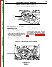
COMMANDER 400
J2
J6
J5
J8
J7
J1
J4
J22
J20
C112
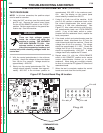
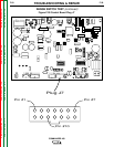
Figure F.27 Control Board Plug J8 location
Plug J8
Pin #5
Pin #8
Pin #9