


Return to Master TOC Return to Master TOC Return to Master TOC Return to Master TOC
Section F-1 Section F-1
COMMANDER 400
Troubleshooting & Repair Section ................................................................................Section F
How to Use Troubleshooting Guide.......................................................................................F-2
PC Board Troubleshooting Procedures .................................................................................F-3
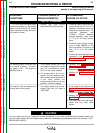
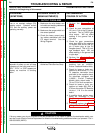
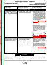
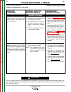
Troubleshooting Guide................................................................................................F-4 - F-15
Initialization Sequence and Commander 400 Error Code Explanations .............................F-16
Error Codes with G2713-I Control Board ......................................................................F-17
Error Codes with G2713-2 or -3 Control Boards...........................................................F-21
Test Procedures...................................................................................................................F-27
Case Cover Removal and Replacement Procedure .....................................................F-27
Case Front Knobs - Removal and Replacement Procedure.........................................F-32
Idler Solenoid Test.........................................................................................................F-33
Shutdown Solenoid Test................................................................................................F-35
Engine Throttle Adjustment Test....................................................................................F-37
Static SCR/Diode Rectifier Bridge Test .........................................................................F-41
Active SCR Test.............................................................................................................F-45
Charging Circuit Test .....................................................................................................F-49
Stator Voltage Test ........................................................................................................F-51
Fine Control Potentiometer Test....................................................................................F-55
Range Switch Test.........................................................................................................F-57
Shunt Calibration Test ...................................................................................................F-61
Exciter Voltage Feedback Test......................................................................................F-63
Exciter Capacitor Bank Test ..........................................................................................F-65
Control Board Power Supply Test .................................................................................F-67
Stator Resistance Test ..................................................................................................F-69
Oscilloscope Waveforms......................................................................................................F-72
Normal Open Circuit Voltage Waveform (115 VAC Supply)..........................................F-72
Normal Open Circuit Voltage Waveform (Stick) Max Tap .............................................F-73
Normal Weld Voltage Waveform (Stick CC) Machine Loaded
to 400 Amps at 40 Volts ..............................................................................................F-74
Normal Weld Voltage Waveform (Wire CV) Machine Loaded
to 400 Amps at 40 Volts ..............................................................................................F-75
Normal Open Circuit Voltage Waveform (Wire CV Tap)................................................F-76
Normal Solenoid Pull & Hold Coil Waveforms ..............................................................F-77
Abnormal Solenoid Pull & Hold Coil Waveforms...........................................................F-78
Typical Exciter Voltage Feedback Waveforms ..............................................................F-79
Abnormal Exciter Voltage Feedback Waveforms..........................................................F-80
Replacement Procedures ....................................................................................................F-81
Control PC Board Removal, Replacement, and Calibration .........................................F-81
Shutdown Solenoid Removal and Replacement...........................................................F-85
SCR/Diode Rectifier Bridge Removal and Replacement ..............................................F-89
SCR Removal and Replacement ..................................................................................F-95
Mounting Stud Type Diodes to Aluminum Heat Sinks.................................................F-103
Engine, Stator/Rotor Removal and Replacement .......................................................F-105
Retest After Repair.............................................................................................................F-117
TABLE OF CONTENTS
TROUBLESHOOTING & REPAIR SECTION