


Return to Section TOC Return to Section TOC Return to Section TOC Return to Section TOC
Return to Master TOC Return to Master TOC Return to Master TOC Return to Master TOC
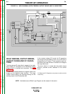
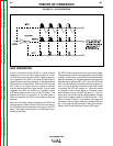
TROUBLESHOOTING & REPAIR
F-6 F-6
Commander 400
Observe Safety Guidelines
TROUBLESHOOTING GUIDE
detailed in the beginning of this manual.
CAUTION
If for any reason you do not understand the test procedures or are unable to perform the test/repairs safely, con-
tact the Lincoln Electric Service Department for electrical troubleshooting assistance before you proceed. Call 1-
800-833-9353 (WELD).
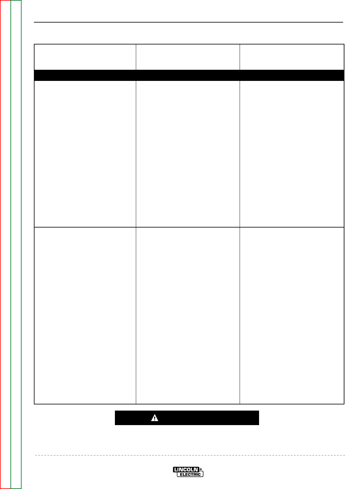
PROBLEMS
(SYMPTOMS)
POSSIBLE AREAS OF
MISADJUSTMENT(S)
RECOMMENDED
COURSE OF ACTION
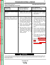
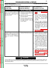
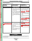
OUTPUT PROBLEMS
The machine powers down within
seconds of power up and all lamp
indicators on the front panel are lit.
“ECL”, “ECH”, or “CSS” appears on
display as machine is shutting
down.
1. Contact your local Lincoln
Authorized Field Service Shop.
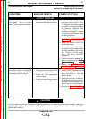
1. Check to make sure that the
machine has an L10953-1
Exciter Feedback Module Asbly.
2. Check for loose or faulty con-
nections or wires at the T1, T2 or
T3 capacitor connection block
and back to the capacitor bank.
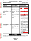
On machines equipped with
L10953-1 Exciter Feedback
Module Asbly check leads T1,
T2 and T3 for fault connections.
3. Check for loose or faulty con-
nections at leads 268, 269, &
270 from the exciter PC Board to
J4 pins 1, 2 & 3 on the control
board.
4. If possible check exciter wave-
forms as illustrated in the
Oscilloscope Waveforms
Section.
5. If possible perform the Exciter
Voltage Feedback Test.
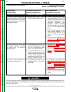
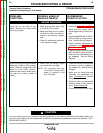
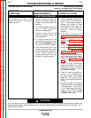
Low or no constant voltage (CV)
welding output. Constant current
(CC) and the auxiliary power are
operating normally.
1. Make sure the wire feeder, con-
trol cable and welding cables are
connected correctly.
2. Make sure the range switch is in
the correct position.
3. Check the heavy current carry-
ing cables associated with the
CV output terminal. See the
Wiring Diagram.
1. Perform the Range Switch
Test.
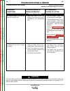
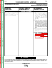
2. Check for poor connections at
J21 pins 1 & 4 at the CV daugh-
ter board. This is CVSCR gate
drive output. Will not affect
welding in the general fab or
pipe taps.
3. Check for poor connections
along lead #208 at the negative
CV output stud and at the J21
pin 6 molex plug at the CV
daughter board. This is CV volt-
age feedback input. Will not
affect welding in the general fab
or pipe taps.
4. Perform the Control Board
Power Supply Test.