


TROUBLESHOOTING & REPAIR
F-87 F-87
COMMANDER 400
Return to Section TOC Return to Section TOC Return to Section TOC Return to Section TOC
Return to Master TOC Return to Master TOC Return to Master TOC Return to Master TOC
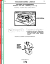
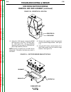
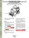
SHUTDOWN SOLENOID REMOVAL AND REPLACEMENT (continued)
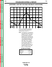
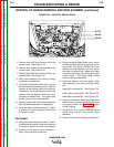
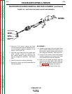
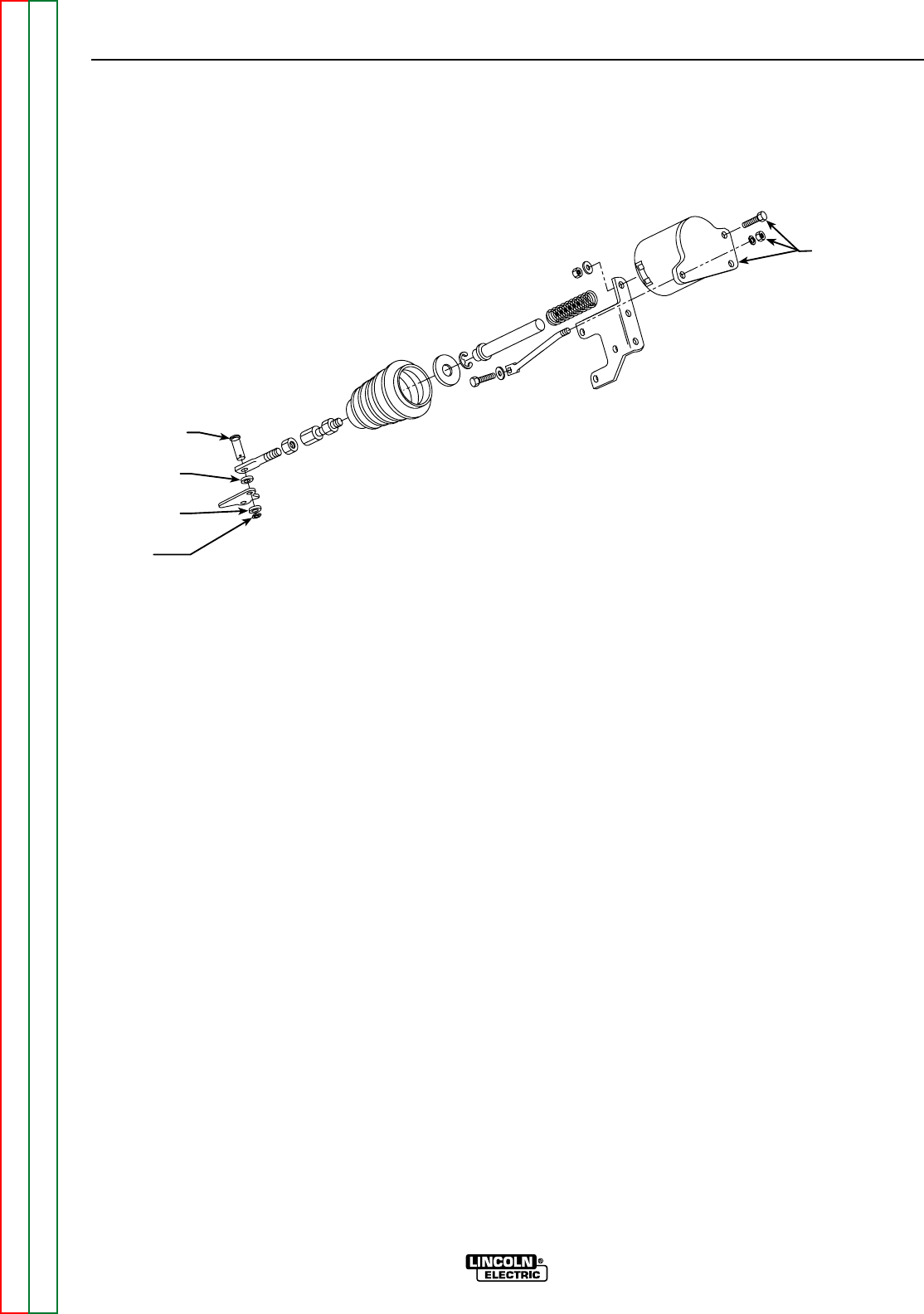
FIGURE F.36 – SHUTDOWN SOLENOID LINKAGE ARM ASSEMBLY
PIVOT PIN
SPACER
WASHER
PLAIN
WASHER
RETAINING
RING
MOUNTING
FASTENERS
4. Using the 7/16" wrench, remove the three
nuts, two bolts and three lock washers mount-
ing the shutdown solenoid assembly to the
engine. See Figure F.36.
5. Using the long screw driver and needle nose
pliers, carefully remove the retaining ring,
plain washer, spacer washer and pivot pin
from the linkage arm assembly. See Figure
F.36.
6. Carefully remove the solenoid assembly.
7. Replace any faulty parts and reassemble the
solenoid assembly.
REASSEMBLY
8. Using the long screw driver and needle nose
pliers, carefully assemble the retaining ring,
plain washer, spacer washer and pivot pin to
the linkage arm assembly. See figure F.36.
9. Using the 7/16" wrench, mount the shutdown
solenoid assembly to the engine with three
nuts, two bolts and three lock washers.
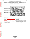
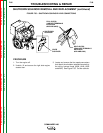
10. Attach the four spade connectors from the
wiring harness leads (#224, #240, #225 and
#262) to the shutdown solenoid terminals.
See Figure F.35. Replace the cable tie.
11. Close the right side engine access door.