


ELECTRIC SHOCK can kill.
• Do not operate with panels open.
• Disconnect NEGATIVE (-) BATTERY
LEAD before servicing.
• Do not touch electrically live parts.
MOVING PARTS can injure.
• Keep guards in place.
• Keep away from moving parts.
• Only qualified personnel should install,
use or service this equipment.
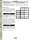
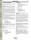
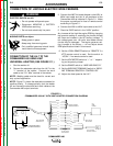
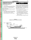
CONNECTION OF THE LN-7 TO THE
COMMANDER 400 USING K867
UNIVERSAL ADAPTER (SEE FIGURE C.1.)
1. Shut the welder off.
2. Connect the electrode cable from the LN-7 to the
“+” terminal of the welder. Connect the work
cable to the “CV- Wire” terminal of the welder.
NOTE: Welding cable must be sized for current and
duty cycle of application.
NOTE: Figure C.1 shows the electrode connected for
positive polarity. To change polarity, shut the welder
off and reverse the electrode and work cables at the
Commander 400 output terminals.
3. Connect the K867 Universal Adapter to the K291 or
K404 input cable and the 14 pin amphenol of the
Commander 400 as indicated in Figure C.1. Make
the proper connections for local or remote control
according to Figure C.1.
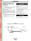
4. Connect the K291 or K404 input cable to the LN-7.
5. Place the IDLER switch in the “HIGH” position.
Any increase of the high idle engine RPM by changing
the governor setting or overriding the throttle linkage
will cause an increase in the AC auxiliary voltage. If
this voltage goes over 140 volts, wire feeder control
circuits may be damaged. The engine governor set-
ting is preset at the factory — do not adjust above
RPM specifications listed in this manual.
6. Set the LOCAL/REMOTE switch to “REMOTE” if a
K775 remote control is used. Set the switch to
“LOCAL” if no remote control is used.
7. Set the VOLTMETER switch to “+” or “-” depend-
ing on the polarity chosen.
8. Set the RANGE switch to “WIRE WELDING CV.”
9. Set the WELDING TERMINALS switch to “WELD-
ING TERMINAL REMOTELY CONTROLLED.”
10. Adjust wire feed speed at the LN-7.
ACCESSORIES
C-3 C-3
COMMANDER 400
Return to Section TOC Return to Section TOC Return to Section TOC Return to Section TOC
Return to Master TOC Return to Master TOC Return to Master TOC Return to Master TOC
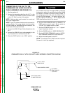
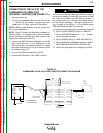
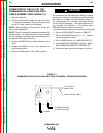
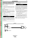
CONNECTION OF LINCOLN ELECTRIC WIRE FEEDERS
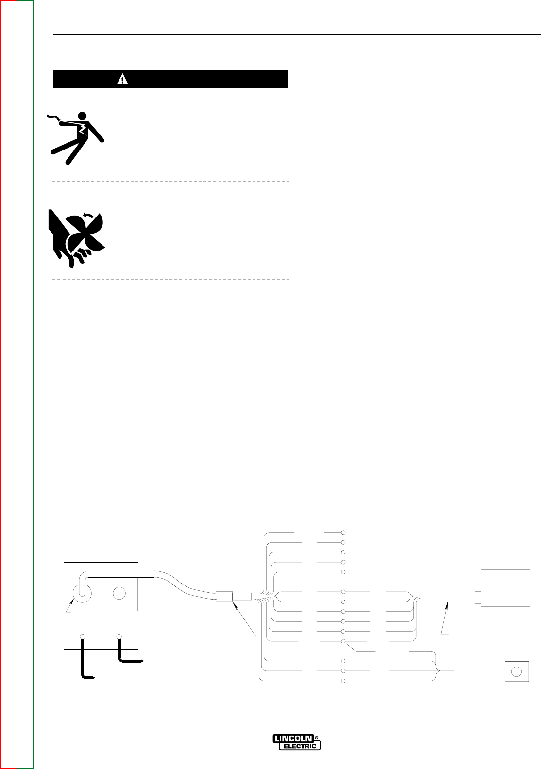
FIGURE C.1
COMMANDER 400/LN-7 WITH K867 ADAPTER CONNECTION DIAGRAM
GND
75
76
77
GREEN
K291 OR K404
75
INPUT CABLE
76
SPLICE LEADS
AND INSULATE
77
TO WORK
K775 OPTIONAL
REMOTE CONTROL
14 PIN
81
42
41
31
31
32
32
2
2
4
4
21
21
GND
82
INSULATE UNUSED
LEADS INDIVIDUALLY
ELECTRODE CABLE
TO WIRE FEED UNIT
LN-7
WIRE
FEEDER
SPARE
}
}
AMPHENOL
CV-
+
K867 UNIVERSAL
ADAPTER PLUG
WARNING