


TROUBLESHOOTING & REPAIR
F-54 F-54
COMMANDER 400
Return to Section TOC Return to Section TOC Return to Section TOC Return to Section TOC
Return to Master TOC Return to Master TOC Return to Master TOC Return to Master TOC
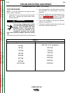
STATOR VOLTAGE TEST (continued)
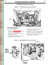
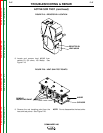
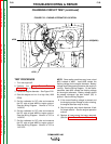
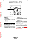
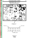
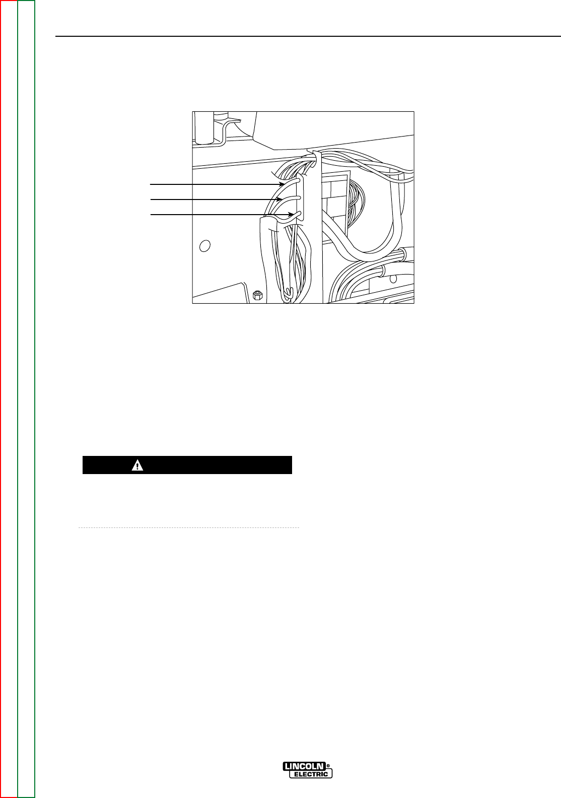
FIGURE F.26 – EXCITER LEADS T1, T2, T3
WARNING
T1
T2
T3
TEST PROCEDURE – Exciter Winding
Voltage Test
11. Turn the engine off.
12. Locate the exciter leads T1, T2 and T3. See
Figure F.26.
13. Carefully pierce the insulation on leads T1,
T2 and T3 for voltage measurements.
Make the smallest possible puncture away from
any sheet metal parts. Reinsulate these punc-
tures at the end of this test.
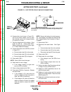
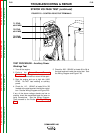
14. Start the engine and run it at high idle (1900
RPM).
15. Using the voltmeter carefully check for 460
- 550VAC from T1 to T2.
16. Using the voltmeter carefully check for 460
- 550VAC from T2 to T3.
17. Using the voltmeter carefully check for 460
- 550VAC from T3 to T1.
If the Exciter Winding Voltage Test is OK and any
of the other voltage checks are low or missing,
the stator may be faulty. Check for "shorted" or
"grounded" windings in the stator.
If the exciter voltages are low or missing, the
capacitors or associated leads may be faulty.
Check for grounded or shorted windings. See the
Wiring Diagram.
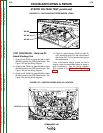
18. Replace the front shroud and all case covers
that were removed. (See the Case Cover
Removal Procedure.)
CAUTION