Return to Section TOC Return to Section TOC Return to Section TOC Return to Section TOC
Return to Master TOC Return to Master TOC Return to Master TOC Return to Master TOC
TROUBLESHOOTING & REPAIR
F-42 F-42
COMMANDER 400
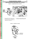
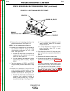
STATIC SCR/DIODE RECTIFIER BRIDGE TEST (continued)
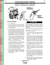
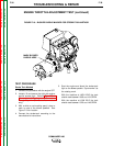
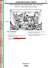
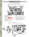
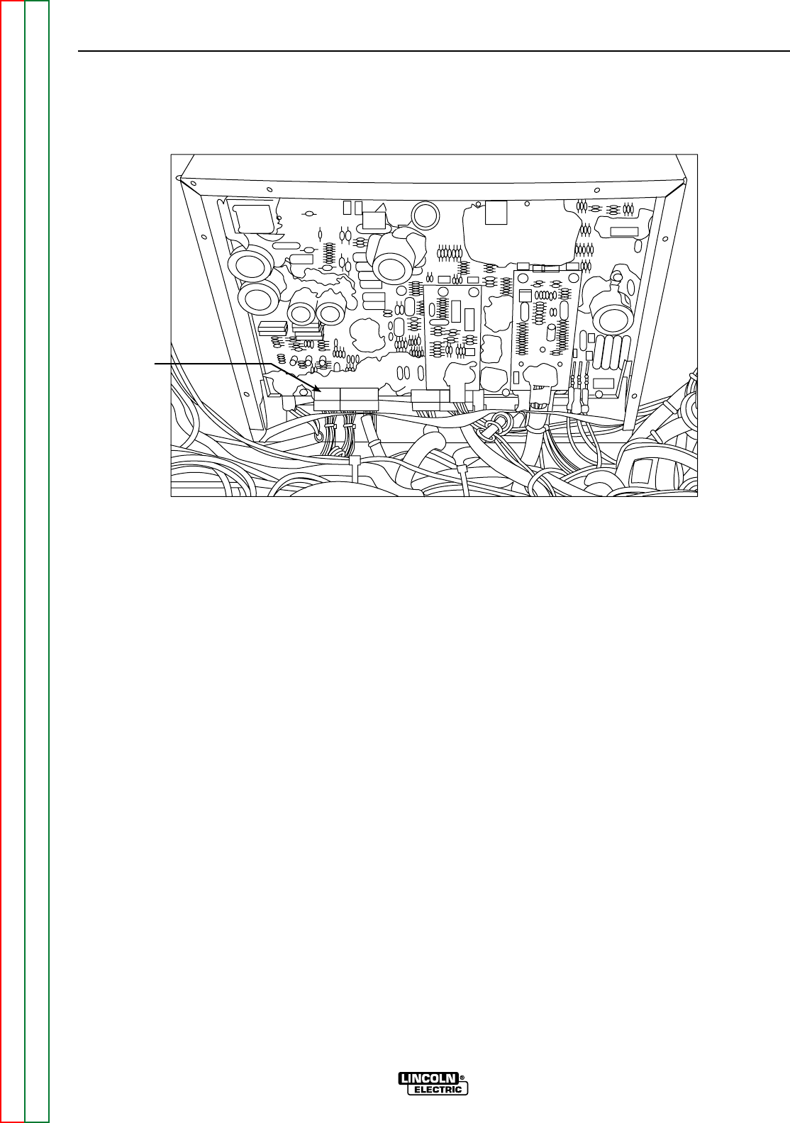
FIGURE F.13 – CONTROL BOARD PLUG J6 LOCATION
PLUG J6
P e l 9 9 6
TEST PROCEDURE
1. Turn off the engine.
2. Disconnect the welding cables from the
welding output terminals.
3. Perform the Case Removal Procedure
(including front shroud removal).
4. Using the 5/16” nut driver, remove the control
board cover. See Figure F.13.
5. Locate and remove molex plug J6 from the
control board. See Figure F.13.


