


TROUBLESHOOTING AND REPAIR
RANGE SWITCH TEST (continued)
Return to Section TOC Return to Section TOC Return to Section TOC Return to Section TOC
Return to Master TOC Return to Master TOC Return to Master TOC Return to Master TOC
TEST PROCEDURE
NOTE: In this test procedure, the positive output
stud is used for common.
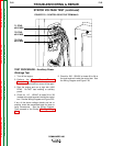
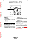
1. Using the 5/16” nut driver, open the control panel
and tilt out. Remove the control board cover.
Start the machine.
There are high voltages present inside
the control box while the machine is
running. THE VOLTAGES ARE HIGH
ENOUGH TO KILL. Use extreme cau-
tion to avoid the backside of the
receptacles, breakers, and terminal
strip while checking voltages inside the control
box.
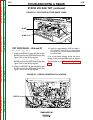
2. Put the range switch in the CV position on stick &
wire machines, or in the 90 tap on stick only
machines.
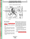
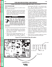
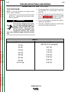
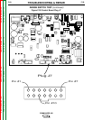
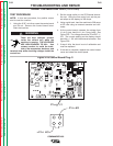
3. Check the voltage at the control board from J7
pin 10 to common at each tap on the range
switch. See Figure F.28. See table F.1 below for
approximate voltage reading from each tap.
4. If any of the voltages in the table are incorrect,
replace the range switch.
5. If the test is complete, replace the control board
cover and close the control panel.
WARNING
CV tap
90 tap
120 tap
180 tap
230 tap
270 tap
400 tap
50-575 tap
.580 Vdc (if so equipped)
.937 Vdc
1.29 Vdc
1.65 Vdc
2.00 Vdc
2.36 Vdc
2.69 Vdc
3.06 Vdc
Range Switch Position
V
oltage
F-58 F-58
COMMANDER 400
Table F.1