


TROUBLESHOOTING AND REPAIR
SHUNT CALIBRATION TEST (continued)
Return to Section TOC Return to Section TOC Return to Section TOC Return to Section TOC
Return to Master TOC Return to Master TOC Return to Master TOC Return to Master TOC
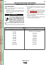
TEST PROCEDURE
NOTE: In this test procedure, the positive output
stud is used for common.
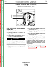
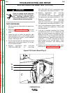
1. Using the 5/16” nut driver, open the control panel
and tilt out. Remove the control board cover.
Start the machine.
There are high voltages present
inside the control box while the
machine is running. THE VOLTAGES
ARE HIGH ENOUGH TO KILL. Use
extreme caution to avoid the back-
side of the receptacles, breakers, and
terminal strip while checking voltages inside the
control box.
2. Set the range switch to the CC/General fabrica-
tion tap. Using the fine control pot, set the pre-
set amps on the display to 300 amps.
3. Using a grid bank, load the machine to 300 amps
at 25 volts using an external ammeter and volt-
meter.
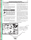
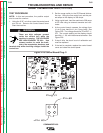
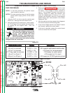
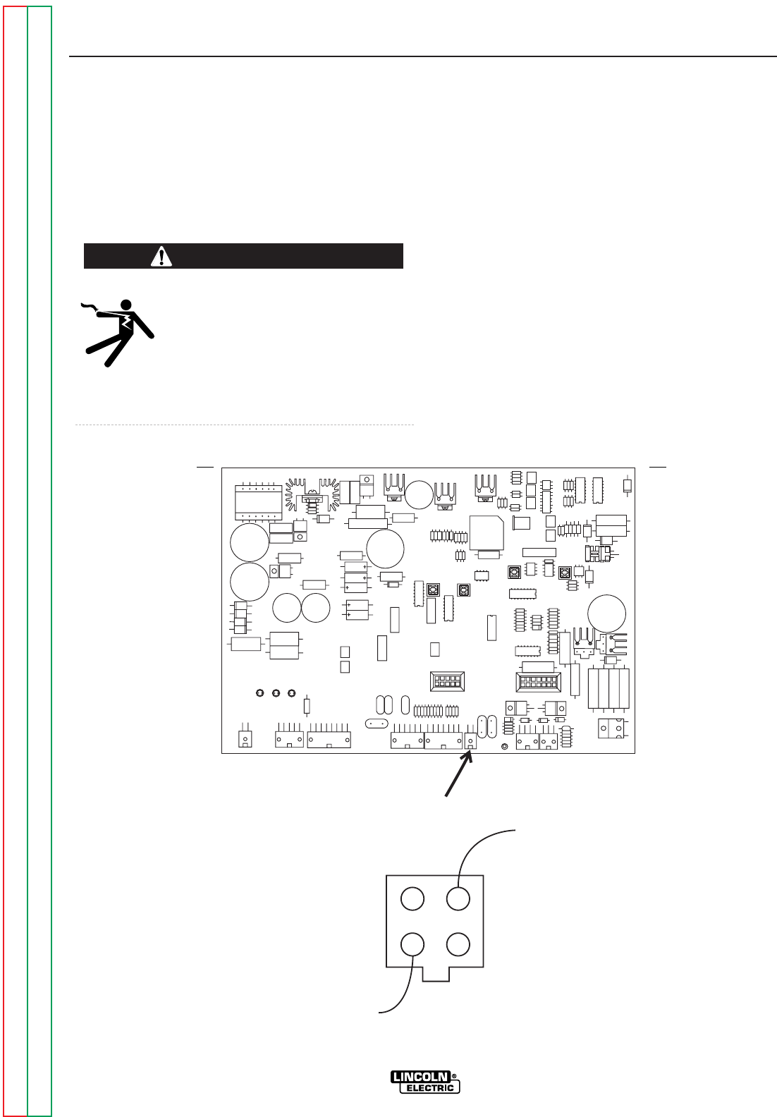
4. At the control board, measure the voltage from
J1 pin 3 (pos. lead) to J1 pin 2 (neg. lead). See
Figure F.29. The voltage should be 25 mVDC +/-
5%. The current reading on the display should
be within +/- 5% with the external ammeter. See
Figure F.29.
5. If step 4 fails, the shunt is out of calibration and
must be replaced.
6. If the test is complete, replace the control board
cover and close the control panel.
WARNING
F-62 F-62
COMMANDER 400
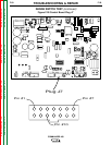
Figure F.29 Control Board Plug J1
J2
J6
J5
J8
J7
J1
J4
J22
J20
C112
-Pin #2
+Pin #3
Plug J1