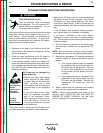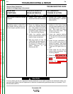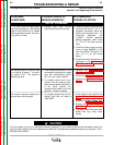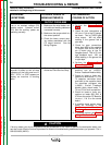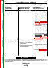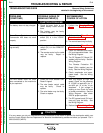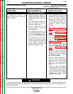
No welding output in either CV or
stick modes. Also no auxiliary
power. Engine operates normally.
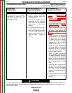
No auxiliary power at receptacles.
The engine operates normally and
the welding output is normal.
1. Contact your local Lincoln
Authorized Field Service Shop.
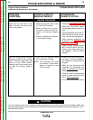
1. Check the circuit breakers CB1
thru CB4. Reset if tripped.
2. Check the GFCI receptacles.
Reset if tripped.
3. Check for loose or faulty plugs at
the power receptacles.
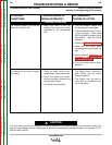
1. Check for loose or faulty con-
nections or wires at the T1, T2 or
T3 capacitor connection block
and back to the capacitor bank.
On machines equipped with
L10953-1 Exciter feedback mod-
ule asbly check leads T1, T2 and
T3 for faulty connections. See
the Wiring Diagram.
2. Perform the Exciter Capacitor
Bank Test.
3. Check for a short across the
weld bridge plates.
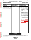
4. Disconnect leads 3, 5 & 6 from
the terminal block located inside
the right hand side of the control
box. Check for a short across
each 115v and 115V/230V
receptacle.
5. Check fro shorts or opens in the
stator by performing the Stator
Resistance Test.
6. Perform the Control Board
Power Supply Test.
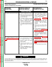
1. Check the GFCI receptacles and
associated wires for loose or
faulty connections. See the
Wiring Diagram.
2. Check the continuity of leads #3,
#5, #5A and #6 from the exciter
windings to their respective tie
points. See the Wiring Diagram.
3. Perform the Stator Voltage Test.
Return to Section TOC Return to Section TOC Return to Section TOC Return to Section TOC
Return to Master TOC Return to Master TOC Return to Master TOC Return to Master TOC
TROUBLESHOOTING & REPAIR
F-7 F-7
COMMANDER 400
TROUBLESHOOTING GUIDE Observe Safety Guidelines
detailed in the beginning of this manual.
CAUTION
If for any reason you do not understand the test procedures or are unable to perform the test/repairs safely, con-
tact the Lincoln Electric Service Department for electrical troubleshooting assistance before you proceed. Call 1-
800-833-9353 (WELD).
PROBLEMS
(SYMPTOMS)
POSSIBLE AREAS OF
MISADJUSTMENT(S)
RECOMMENDED
COURSE OF ACTION
OUTPUT PROBLEMS


