


Return to Section TOC Return to Section TOC Return to Section TOC Return to Section TOC
Return to Master TOC Return to Master TOC Return to Master TOC Return to Master TOC
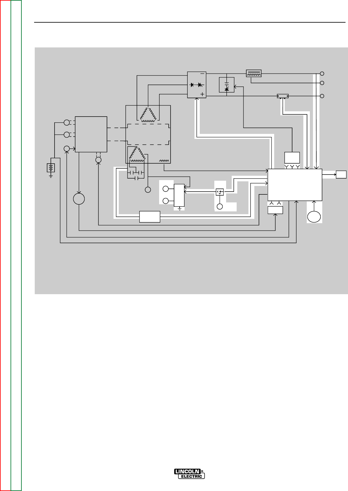
EXCITER FEEDBACK, CONTROL
BOARD, LOCAL AND REMOTE
CONTROL
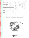
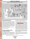
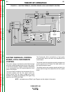
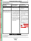
The exciter voltage is monitored and fed back through
the exciter voltage feedback board to the control board.
In the event the exciter voltage increases or decreases
to an unacceptable level, the engine protection circuit
shuts off the engine.
The control board compares the commands of the cur-
rent/mode selector and the fine output control (or
remote control) with the output voltage and current
feedback and sends the appropriate SCR gate firing
signals to the SCR/Diode bridge.
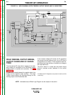
The Commander 400 is controlled by a high quality
microcontroller, which is the main circuit element of the
control board.
The control board also supplies operating voltages and
control signals to the CV board, the meter board, and
the engine protection board.
The remote control and contactor signals are fed to the
control board through the amphenols and the by-pass
board.
THEORY OF OPERATION
E-3 E-3
COMMANDER 400
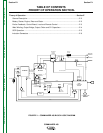
NOTE: Unshaded areas of Block Logic Diagram are the subject of discussion.
FIGURE E.3 – EXCITER FEEDBACK, CONTROL BOARD, LOCAL AND REMOTE CONTROL
ENGINE ROTOR
MECHANICAL
ROTATION
EXCITER
WINDINGS
WELD
WINDINGS
SCR/DIODE
OUTPUT
BRIDGE
OUTPUT
CHOKE
CV
CAPAC
ITORS
SHUNT
POSITIVE
TERMINAL
CV
TERMINAL
TERMINAL
NEGATIVE
EXCITER
CAPACITORS
115/230VAC
RECEPTACLE
14 PIN
AMPHENOL
6 PIN
AMPHENOL
EXCITER VOLTAGE
FEEDBACK
BOARD
ENGINE
PROTECTION
BOARD
CURRENT/ MODE
SELECTOR
SWITCH
BATTERY
STARTER
ALTERNATOR
SHUTDOWN
SOLENOID
IDLER
SOLENOID
SENSORS
ENGINE
FINE
OUTPUT
CONTROL
BY-PASS
PC
BOARD
METER
CV
BOARD
MAIN
CONTROL
BOARD
REMOTE
SWITCH
42VAC
12VDC
SCR GATE SIGNALS
115VAC
FEEDBACK
F
E
E
D
B
A
C
K