


Return to Section TOC Return to Section TOC Return to Section TOC Return to Section TOC
Return to Master TOC Return to Master TOC Return to Master TOC Return to Master TOC
TROUBLESHOOTING & REPAIR
F-5 F-5
COMMANDER 400
TROUBLESHOOTING GUIDE Observe Safety Guidelines
detailed in the beginning of this manual.
CAUTION
If for any reason you do not understand the test procedures or are unable to perform the test/repairs safely, con-
tact the Lincoln Electric Service Department for electrical troubleshooting assistance before you proceed. Call 1-
800-833-9353 (WELD).
PROBLEMS
(SYMPTOMS)
POSSIBLE AREAS OF
MISADJUSTMENT(S)
RECOMMENDED
COURSE OF ACTION
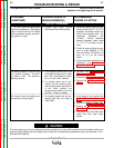
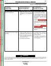
OUTPUT PROBLEMS
The welding output is low with little
or no control of output. The auxil-
iary power is OK. The engine is
operating normal.
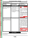
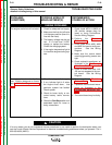
The machine has low welding out-
put and low auxiliary output.
1. If the remote control unit is not
connected to the machine, make
sure the Local/Remote switch
(S1) is in the “Local” position.
2. If a remote control unit is con-
nected, and the machine oper-
ates normally when the switch is
in the “Local” position, the
remote control cable or unit may
be faulty. Check or replace.
1. The engine speed may be low.
Normal high idle (no load) is
1900 RPM.
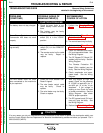
1. Perform the Fine Control
Potentiometer Test.
2. Perform the Stator Voltage Test.
3. Perform the SCR/Diode Bridge
Test.
1. If the speed is low, perform the
Engine Throttle Adjustment
Test.
2. Perform the Stator Voltage Test.
3. Perform the Exciter Capacitor
Bank Test.
4. The engine may have lost horse-
power and may need major
repairs.
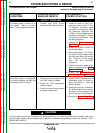
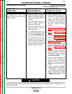
“---” or “CRS” stuck on display when
machine is powered up. No welding
output in both stick and CV modes.
Engine operates normally and auxil-
iary power is normal.
1. Contact your local Lincoln
Authorized Field Service shop.
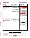
1. Check for loose or faulty connec-
tions or wires at the T1, T2, or T3
capacitor connection block and
back to the capacitor bank. On
machines equipped with
L10953-1 Exciter feedback
Module Assembly check leads
T1, T2 & T3 for faulty connec-
tions.
2. Check for loose or faulty connec-
tions at leads 268,269, & 270
from the exciter PC board to J4
pins 1,2, & 3 on the control
board.
3. Check the exciter waveforms as
illustrated in the Oscilloscope
Waveforms Section.