


Return to Section TOC Return to Section TOC Return to Section TOC Return to Section TOC
Return to Master TOC Return to Master TOC Return to Master TOC Return to Master TOC
TROUBLESHOOTING & REPAIR
F-44 F-44
COMMANDER 400
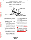
STATIC SCR/DIODE RECTIFIER BRIDGE TEST (continued)
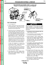
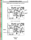
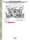
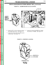
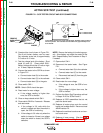
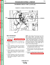
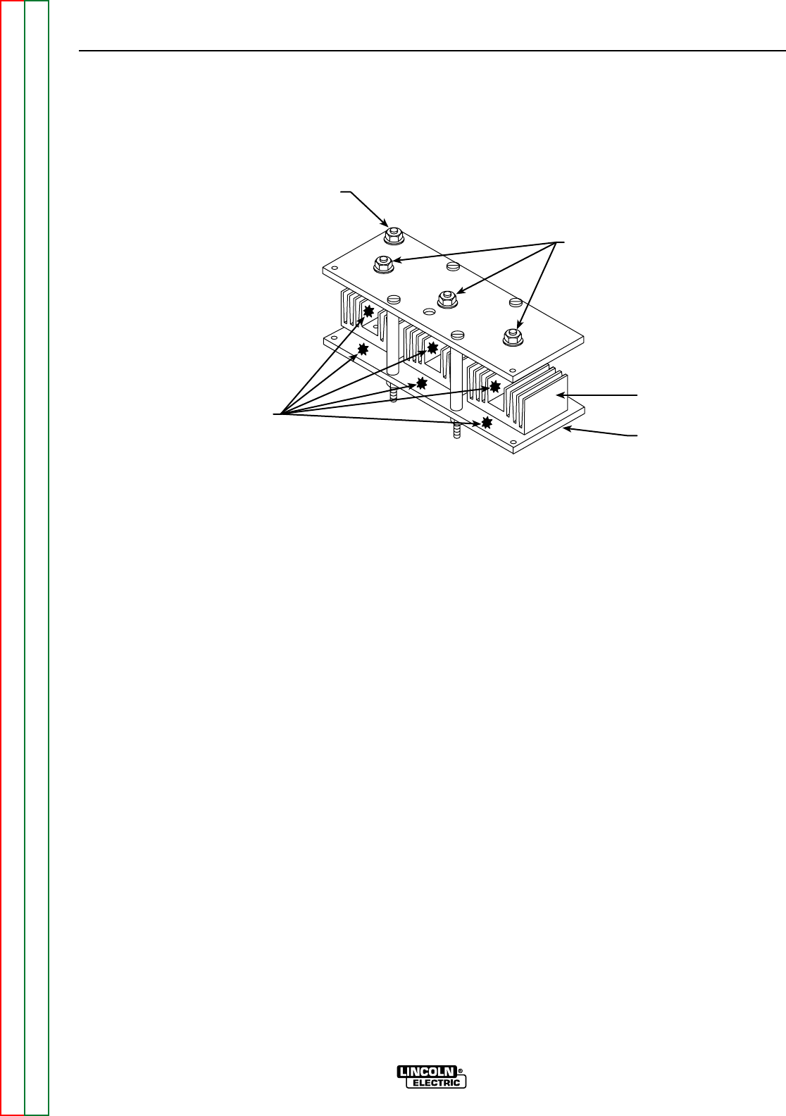
FIGURE F.16 – HEAT SINK AND SCR TEST POINTS
ANODE
CATHODE
DIODE DD
REMOVE
INSULATING PAINT
DIODES DA, DB, DC
9. Remove the red insulating paint from the
heat sink test points. See Figure F.16.
NOTE: Do not disassemble the heat sink.
10. Measure the resistance from the anode to
the cathode of SCR A, using an analog
volt/ohmmeter (multimeter) set at R x 1000
scale. See Figure F.16.
a. Reverse the meter leads and measure the
resistance from the cathode to the anode
of SCR A. See Figure F.16.
b. If a low resistance is measured in either
meter polarity, SCR A is faulty. Replace
SCR A.
11. Test the resistance of SCR B and SCR C
using the same procedure described in Step
10.
12. Measure the resistance of diode DD from
anode (+probe) to cathode (-probe) using an
analog ohmmeter set at R x 1000 scale. The
resistance should be low. See Figure F.16.
a. Reverse the meter leads and measure the
resistance from cathode (+probe) to
anode (-probe) of diode DD. The resis-
tance should be high. See Figure F.16.
b. If a low resistance is measured in both
meter polarities, diode DD is shorted.
Replace diode DD.
c. If a high resistance is measured in both
meter polarities, diode DD is open.
Replace diode DD.
13. Test diodes DA, DB and DC for proper oper-
ation using the same procedure described in
Step 12.
14. Reconnect all leads and molex plugs.
15. If this test did not identify the problem or to
further test the SCRs, go to the Active SCR
Test.
If the test is complete, connect plug J6 to the
control board and plug J30 to the snubber
board and reconnect lead #204B to resistor
R1. Replace the covers to the two boards.
Replace all case covers. (See the Case
Cover Removal and Replacement proce-
dure.)