Return to Section TOC Return to Section TOC Return to Section TOC Return to Section TOC
Return to Master TOC Return to Master TOC Return to Master TOC Return to Master TOC
TROUBLESHOOTING & REPAIR
F-18 F-18
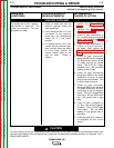
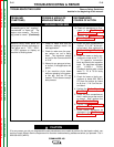
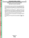
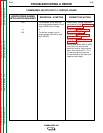
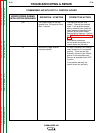
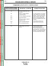
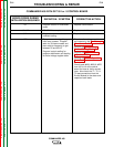
COMMANDER 400 WITH G2713-1 CONTROL BOARD
ERROR CODES DURING
INITIALIZATION SEQUENCE
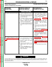
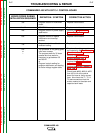
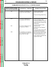
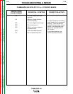
DEFINITION / SYMPTOM CORRECTIVE ACTION
CSS
or
ECL
The processor is not receiving
zero cross signals properly or the
engine RPM is out of range.
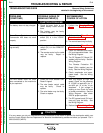
or
The exciter voltage is out of
range (greater than 550 or less
than 140VAC).
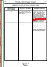
Check exciter voltage waveforms
as illustrated in the Oscilloscope
Waveforms Section.
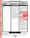
Perform the Stator Voltage
Exciter Winding Test.
Perform the Engine Throttle
Adjustment Test.
Perform the Exciter Capacitor
Bank Test.
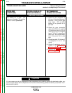
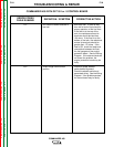
Check leads #268, #269, & #270
from J50 to J4 at the control
board for loose or faulty connec-
tions. Also check the T1, T2, &
T3 lead connections from the
Exciter Module to the stator and
capacitor bank leads.
COMMANDER 400


