


Return to Section TOC Return to Section TOC Return to Section TOC Return to Section TOC
Return to Master TOC Return to Master TOC Return to Master TOC Return to Master TOC
OPERATION
B-5 B-5
COMMANDER 400
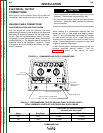
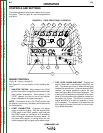
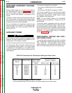
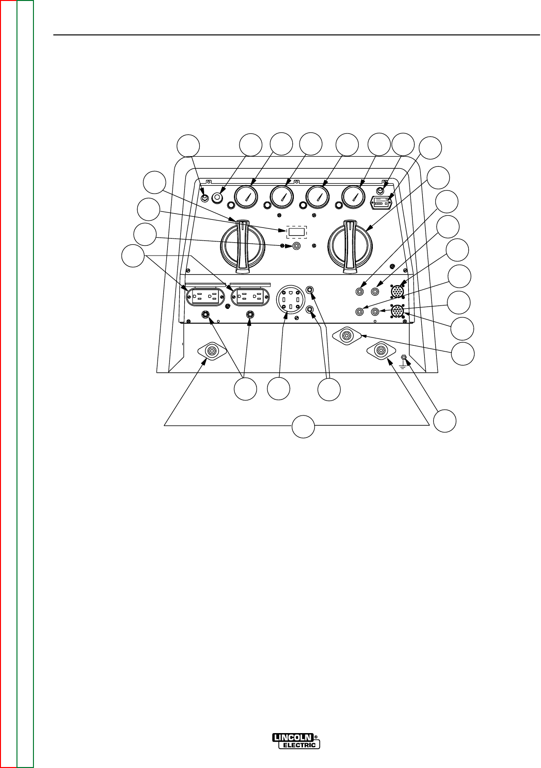
FIGURE B.1 – CASE FRONT PANEL CONTROLS
ENGINE CONTROLS
(Figure B.1, Items 1 through 8)
See Figure B.1 for the location of the following fea-
tures:
1. RUN-STOP SWITCH: When placed in the “RUN”
position, this switch energizes the fuel solenoid and
other electric accessories. When placed in the
“STOP” position, the flow of fuel to the injection
pump is stopped to shut down the engine.
NOTE: If the switch is left in the “RUN” position and
the engine is not running, the battery will be drained by
the fuel solenoid.
2. START PUSHBUTTON: Energizes the starter
motor to crank the engine. With the engine RUN-
STOP switch in the “RUN” position, push and hold
the START button for a minimum of 2 seconds to
crank the engine; release as the engine starts. Do
not press while engine is running since this can
cause damage to the ring gear and/or starter motor.
3. FUEL LEVEL GAUGE AND LIGHT: Displays the
level of diesel fuel in the 25-gallon (94.6 liter) fuel
tank. The yellow light turns on when the fuel gage
reaches the reserve level. Once the reserve level is
reached, the engine protection system will shut
down the engine after 30 minutes of operation. The
machine can be restarted and operated for an addi-
tional 30 minutes before the protection system will
shut down the engine. This ability to override the
engine protection is to allow the operator to “finish
up” if necessary. The operator must watch the fuel
level closely to prevent running out of fuel and hav-
ing to bleed the system.
CONTROLS AND SETTINGS
The welder/generator controls are located on the case
front panel. Refer to Figure B.1 and the explanations
that follow.
0
OIL
2
9
17
23
00000
8
7
16
15
18
FUEL
TEMP
4
AMPS
5
6
PRESS
9
HOURS
13
22
21
24
20
3
1
10
11
12
19
14
+-
-