


TROUBLESHOOTING & REPAIR
F-79 F-79
COMMANDER 400
Return to Section TOC Return to Section TOC Return to Section TOC Return to Section TOC
Return to Master TOC Return to Master TOC Return to Master TOC Return to Master TOC
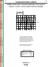
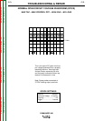
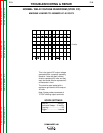
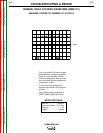
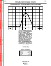
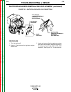
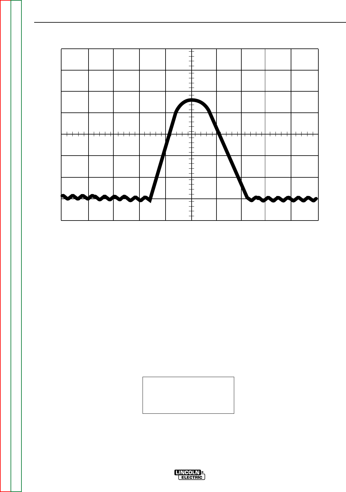
TYPICAL EXCITER VOLTAGE FEEDBACK WAVEFORMS
1 V
2 ms
This is the typical waveform output
from each of the three phases from
the Exciter Feedback Module
(L10953-1) at high idle/no load under
normal operation. The peak should
measure between 3.5 - 4.5 Vdc, and
the period should measure approxi-
mately 8.0 - 9.0 ms (make sure that
the machine is set up to the proper
high idle rpm before making this
measurement by performing the
Engine Throttle Adjustment Test).
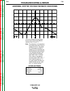
This waveform can be viewed at the
following points on the control board:
J4 pin 1 to pin 7
J4 pin 2 to pin 7
J4 pin 3 to pin 7
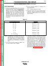
SCOPE SETTINGS
Volts/Div.......................1V/Div.
Horizontal ..................2ms/Div.
Coupling.............................DC
Trigger.........................Internal