


Return to Section TOC Return to Section TOC Return to Section TOC Return to Section TOC
Return to Master TOC Return to Master TOC Return to Master TOC Return to Master TOC
TROUBLESHOOTING & REPAIR
F-31 F-31
COMMANDER 400
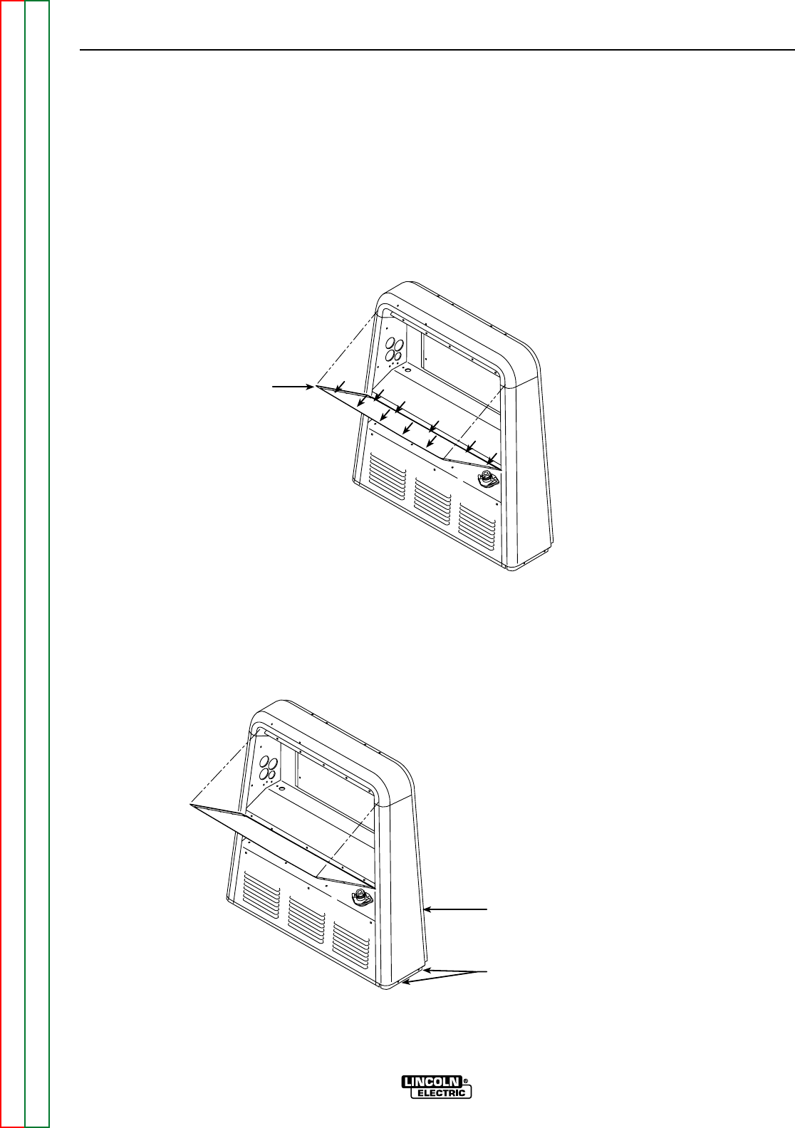
FRONT CONTROL
PANEL LOWERED
ARROWS INDICATE
SCREW LOCATIONS
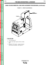
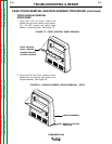
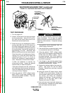
FIGURE F.5 – FRONT CONTROL PANEL REMOVAL
FRONT SHROUD REMOVAL
PROCEDURE
1. Using the 5/16" nut driver, remove the
screws from the front control panel assem-
bly. Do NOT remove the phillips head
screws. Lower the panel. See Figure F.5.
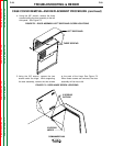
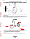
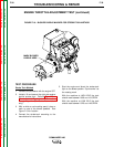
CASE COVER REMOVAL AND REPLACEMENT PROCEDURE (continued)
REMOVE 2 SCREWS,
EACH SIDE
SHROUD ASSEMBLY
FIGURE F.6 – SHROUD ASSEMBLY SCREW REMOVAL - SIDES
2. Using the 5/16" nut driver, remove the four
screws from the left and right sides of the
shroud assembly. See Figure F.6.