


TROUBLESHOOTING & REPAIR
F-92 F-92
COMMANDER 400
Return to Section TOC Return to Section TOC Return to Section TOC Return to Section TOC
Return to Master TOC Return to Master TOC Return to Master TOC Return to Master TOC
SCR/DIODE RECTIFIER BRIDGE
REMOVAL AND REPLACEMENT (continued)
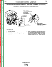
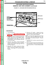
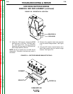
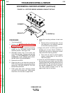
FIGURE F.40 – RESISTOR R1 LOCATION
RESISTOR R1
LEAD #204B
12. Using the 11/32" wrench, remove the #204B
lead from the R1 (50 Ohm -100 Watt) resis-
tor. See Figure F.40. Cut any necessary
cable ties and clear leads for SCR/diode rec-
tifier bridge assembly removal.
NOTE: Be sure to replace any cut cable ties on
reassembly. Otherwise, the leads may catch in
the blower.
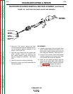
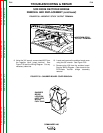
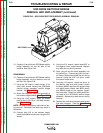
13. Remove the capacitor leads and grommet
from the rectifier bridge bracket. See Figure
F.41.
14. Using the 3/8" wrench, remove the four (2 on
each side) screws from the rectifier bridge
bracket. See Figure F.41.
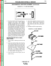
FIGURE F.41 – RECTIFIER BRIDGE BRACKET DETAILS
GROMMET
BRACKET
SCREWS (4)