


Return to Section TOC Return to Section TOC Return to Section TOC Return to Section TOC
Return to Master TOC Return to Master TOC Return to Master TOC Return to Master TOC
TROUBLESHOOTING & REPAIR
F-38 F-38
COMMANDER 400
ENGINE THROTTLE ADJUSTMENT TEST (continued)
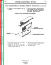
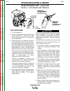
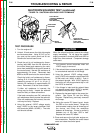
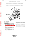
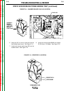
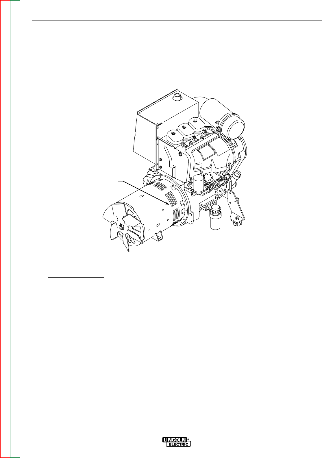
FIGURE F.10 - BLOWER PADDLE MARKED FOR STROBE-TACH METHOD
MARK BLOWER
PADDLE HERE
TEST PROCEDURE
Strobe T
ach Method
1. Conduct this procedure with the engine OFF.
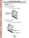
2. Unlatch, lift and secure the right side engine
service access door. Perform Case Cover
Removal and Replacement Procedure
through Step 11. (For Strobe-Tach method
only.)
3. With a white or red marking pencil, place a
mark on one of the blower paddles. See
Figure F.10 for location.
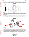
4. Connect the strobe-tach according to the
manufacturer's instructions.
5. Start the engine and direct the strobe-tach
light on the blower paddle. Synchronize it to
the rotating mark.
With the machine at HIGH IDLE the tach
should read between 1890 and 1915 RPM.
With the machine at LOW IDLE the tach
should read between 1325 and 1400 RPM.