


TROUBLESHOOTING & REPAIR
F-113 F-113
COMMANDER 400
Return to Section TOC Return to Section TOC Return to Section TOC Return to Section TOC
Return to Master TOC Return to Master TOC Return to Master TOC Return to Master TOC
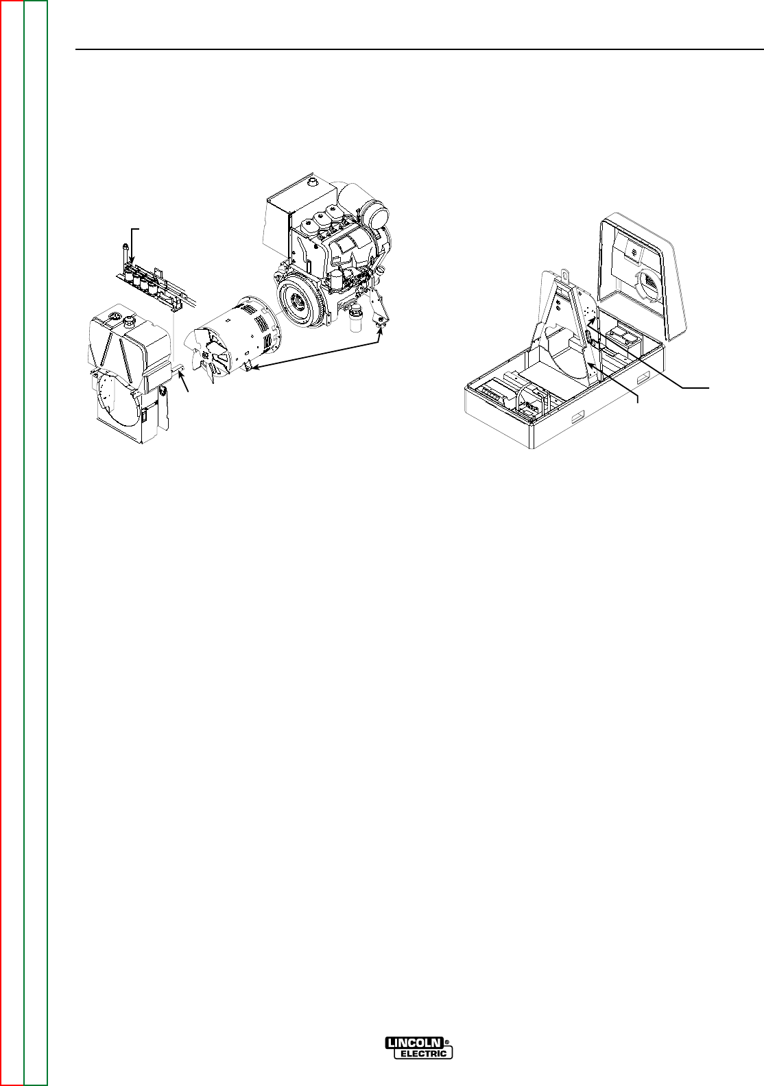
ENGINE, STATOR/ROTOR REMOVAL AND REPLACEMENT (continued)
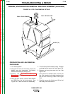
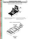
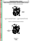
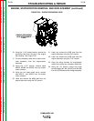
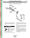
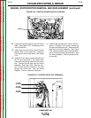
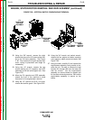
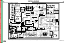
FIGURE F.60 – VERTICAL BAFFLE /ENGINE MOUNT REMOVAL
CV
CAPACITOR
AND SCR
ASSEMBLY
STATOR AND
ENGINE
MOUNTS
FUEL TANK
SUPPORT
RAIL
LIFT
FRAME
VERTICAL
BAFFLE
LIFT FRAME
ASSEMBLY
32. Using the 3/8" wrench, remove the eight
screws that mount the lift frame vertical baf-
fle to the lift frame assembly. See Figure
F. 60. Also remove the engine access door
chain, noting its placement and length for
reassembly.
33. Using the 1/2" wrench, remove the two
screws holding the CV capacitor and SCR
assembly to the fuel tank support rails. See
Figure F.60.
34. Move the CV capacitor and SCR assembly
toward the front of the machine to allow
clearance for the engine/stator removal.
35. Using the 1/2" wrench and 5/16" nut driver,
remove the tank/fan guard. See Figure F.60..
36. Using the 3/4" wrench and socket wrench,
remove the four engine and stator mounting
nuts, spacers, rubber mounts and bolts. See
Figure F.60.
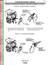
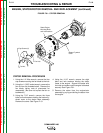
37. Using the hoist, carefully lift and remove the
engine/stator assembly, being careful to bal-
ance the unit. Be sure to remove the lead
bundles W1 through W6 from the lower left
side fan shroud. Set the engine/stator
assembly on secure blocks for support and
for the stator removal procedure. Be sure the
engine/stator assembly is secure on the
blocks.