


TROUBLESHOOTING & REPAIR
F-112 F-112
COMMANDER 400
Return to Section TOC Return to Section TOC Return to Section TOC Return to Section TOC
Return to Master TOC Return to Master TOC Return to Master TOC Return to Master TOC
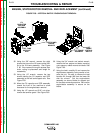
ENGINE, STATOR/ROTOR REMOVAL AND REPLACEMENT (continued)
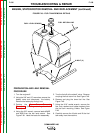
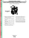
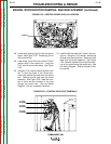
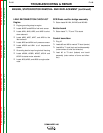
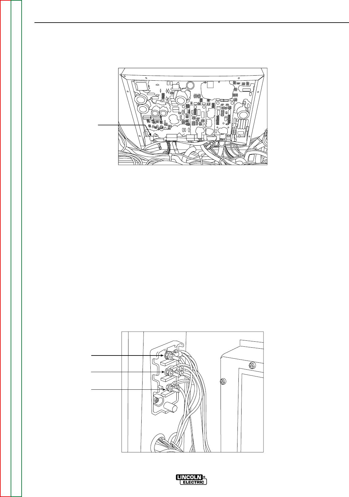
FIGURE F.58 – CONTROL BOARD PLUG J2 LOCATION
PLUG J2
P e l 9 9 6
28. Locate and remove plug J2 from the control
board. See Figure F. 58. Thread plug J2 out
of the control box.
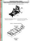
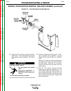
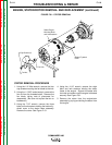
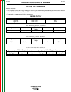
29. Label leads 5 and 5A at the neutral T2 stud
(center stud) in the control box. Using the
7/16" wrench remove the leads. See Figure
F.59.
30. Using the 7/16" wrench remove lead #6 from
the T1 stud (top stud) in the control box.
Label and remove the lead from the control
box. Remove the #6 lead from the toroid
assembly. See Figure F.59. Note the num-
ber of turns and the direction of the lead
through the toroid hole. See the Wiring
Diagram. Cut any necessary cable ties.
31. Label the #3 lead from the T3 stud in the con-
trol box. Using the 7/16" wrench, remove the
#3 lead from the control box. Remove the #3
lead from the toroid assembly. See Figure
F.59. Note the number of turns and the direc-
tion of the lead through the toroid hole. See
the Wiring Diagram. Clear the leads for sta-
tor removal.
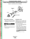
FIGURE F.59 – CONTROL BOX STUD TERMINALS
T1 STUD
#6 LEADS
T2 STUD
#5 LEADS
T3 STUD
#3 LEADS