


Return to Section TOC Return to Section TOC Return to Section TOC Return to Section TOC
Return to Master TOC Return to Master TOC Return to Master TOC Return to Master TOC
GENERAL DESCRIPTION
The Commander 400 is a diesel engine driven welding
power source. The machine uses a brushless asyn-
chronous alternating current generator for DC stick
electrode welding and for 120/240 VAC auxiliary stand-
by power. As a generator it can supply up to 10,000
watts of 120/240 volt AC power. As a welder it provides
up to 400 amps of DC constant current output in six
slope-controlled ranges. In addition a seventh general
purpose welding range provides up to 575 amps of
constant current welding output.
The stick and wire model has a CV terminal for con-
stant voltage wire welding.
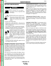
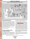
BATTERY, STARTER, ENGINE,
ROTOR AND STATOR
The 12VDC battery powers the engine starter motor
and supplies power to the main control board for the
engine protection circuitry. The engine's alternator
supplies "charging" current for the battery circuit. The
battery circuit also provides power through the main
control board for the idler solenoid, which is mechani-
cally coupled to the engine's throttle linkage.
The diesel engine is coupled to a brushless asynchro-
nous three-phase alternating current induction genera-
tor. See Induction Generators. The excitation or
"flashing" voltage is developed in the exciter windings
and capacitor configuration. The rotor, which is manu-
factured by casting aluminum through steel lamination,
is mechanically coupled to the engine. Through exci-
tation of this rotating magnet, voltages are produced in
the stationary windings of the stator. There are three
separate and isolated sets of windings incorporated in
the stator lamination. Each set has a different number
of turns producing different magnitudes of AC output
voltages. These three windings are the three-phase
weld winding, the three-phase exciter winding; which is
tapped for single phase auxiliary standby power; and
the 42VAC single-phase winding, which supplies power
to the main control board.
The engine protection circuit shuts the engine off in the
event of low oil pressure, engine over temperature,
malfunction in the engine's alternator system, or a low
fuel condition.
THEORY OF OPERATION
E-2 E-2
COMMANDER 400
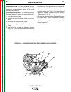
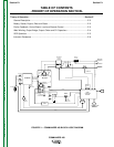
FIGURE E.2 – BATTERY, STARTER, ENGINE, ROTOR AND STATOR
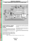
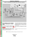
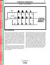
NOTE: Unshaded areas of Block Logic Diagram are the subject of discussion.
ENGINE ROTOR
MECHANICAL
ROTATION
EXCITER
WINDINGS
WELD
WINDING
S
SCR/DIODE
OUTPUT
BRIDGE
OUTPUT
CHOKE
CV
CAPACITO
RS
SHUNT
POSITIVE
TERMINAL
CV
TERMINAL
TERMINAL
NEGATIVE
EXCITER
CAPACITORS
115/230VAC
RECEPTACLE
14 PIN
AMPHENOL
6 PIN
AMPHENOL
EXCITER VOLTAGE
FEEDBACK
BOARD
ENGINE
PROTECTION
BOARD
CURRENT/ MODE
SELECTOR
SWITCH
BATTERY
STARTER
ALTERNATOR
SHUTDOWN
SOLENOID
IDLER
SOLENOID
SENSORS
ENGINE
FINE
OUTPUT
CONTROL
BY-PASS
PC
BOARD
METER
CV
BOARD
MAIN
CONTROL
BOARD
REMOTE
SWITCH
42VAC
12VDC
SCR GATE SIGNALS
115VAC
FEEDBACK
F
E
E
D
B
A
C
K