


TROUBLESHOOTING & REPAIR
F-91 F-91
COMMANDER 400
Return to Section TOC Return to Section TOC Return to Section TOC Return to Section TOC
Return to Master TOC Return to Master TOC Return to Master TOC Return to Master TOC
SCR/DIODE RECTIFIER BRIDGE
REMOVAL AND REPLACEMENT (continued)
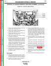
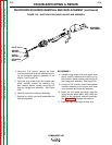
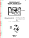
FIGURE F.38 – NEGATIVE “STICK” OUTPUT TERMINAL
#207 FROM STICK
OUTPUT TERMINAL
COMMANDER 400
STICK and WIRE
STICK and WIRE
WIRE
WIRE
STISTI
+
9. Using the 3/4" wrench, remove lead #207 from
the negative "stick" output terminal. See
Figure F.38 and the Wiring Diagram. Cut any
necessary cable ties.
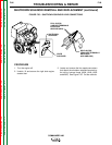
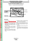
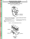
10. Locate and remove the snubber board cover
using the 3/8" wrench. See Figure F.39.
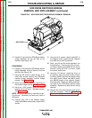
11. Remove plug J30 from the snubber board.
See the Wiring Diagram. Clear leads for the
SCR/diode rectifier bridge assembly
removal.
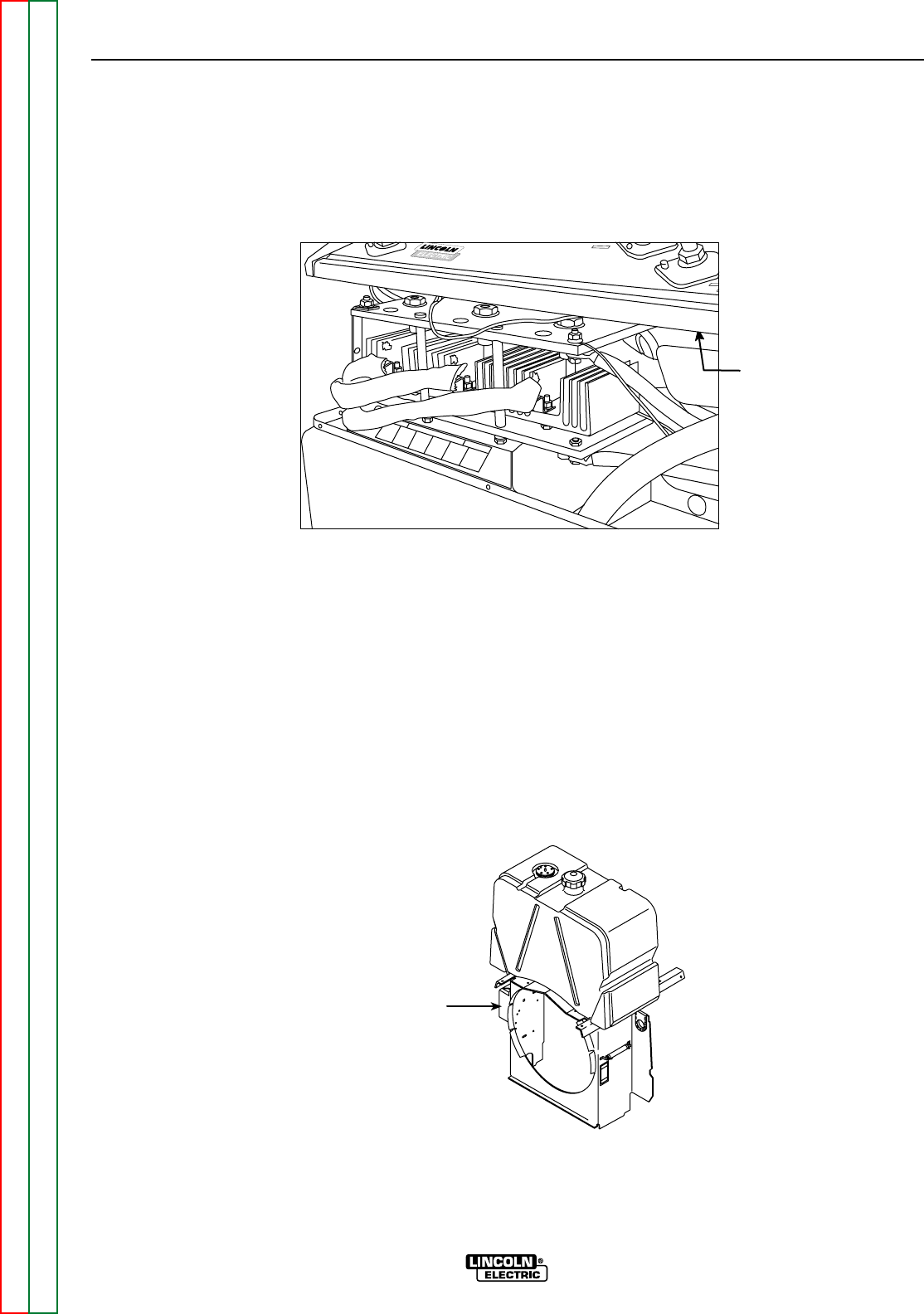
FIGURE F.39 – SNUBBER BOARD COVER REMOVAL
SNUBBER
BOARD
LOCATION
(LEFT SIDE,
BELOW
FUEL TANK)