


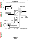
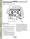
WELDER CONTROLS (Figure B.1 Items 9
through 14 )
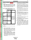
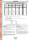
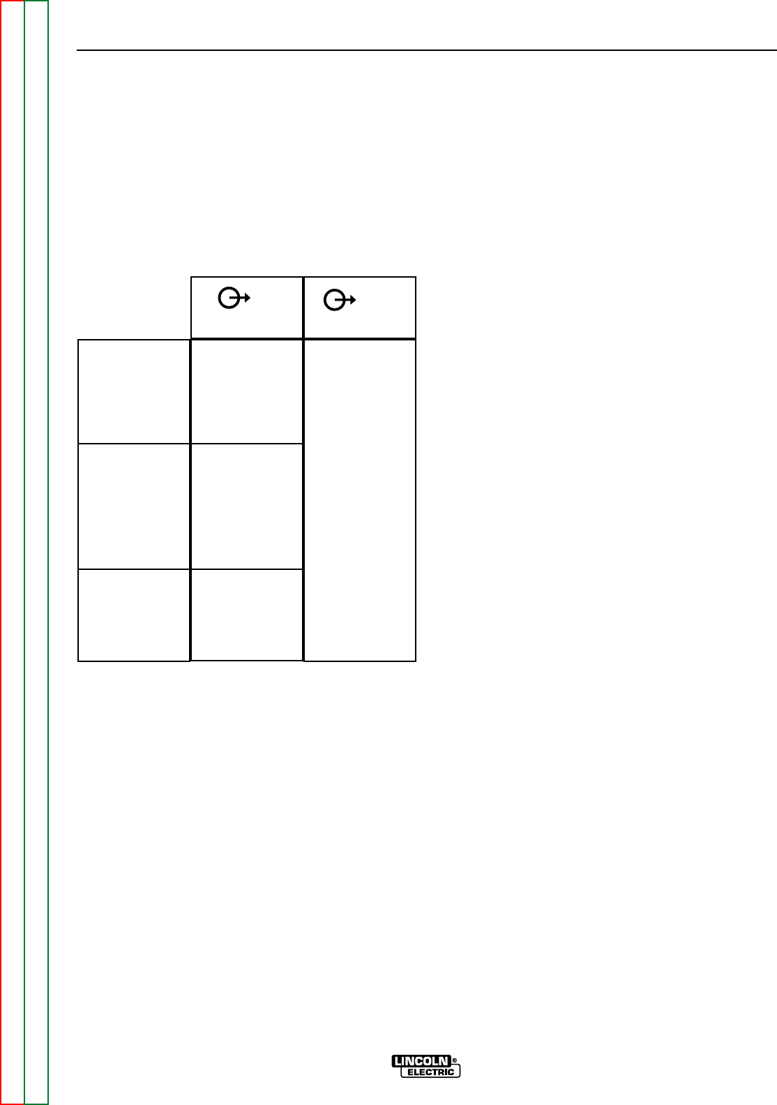
9. OUTPUT RANGE SWITCH AND OUTPUT CON-
TROL: These two controls allow you to select
between various welding output slopes and adjust
the desired welding output. Refer to Table B.1 for a
description of how these two controls work.
TABLE B.1 OUTPUT RANGE SWITCH AND OUT-
PUT CONTROL FUNCTIONS
1
If the OUTPUT RANGE switch is positioned between settings, the
previous setting is maintained until the switch is properly positioned
on a setting.
2
The OUTPUT CONTROL also controls O.C.V. while in the 6 sloped
output ranges.
10. DIGITAL OUTPUT METER: The digital output
meter is located in the center of the control panel
between the two large control knobs. The meter
allows the output current level to be set prior to
welding. During the welding process the meter
displays the actual output current.
11. WELDING TERMINALS SWITCH: The toggle
switch on the control panel labeled “WELDING
TERMINALS ALWAYS ON” and “WELDING TER-
MINALS REMOTELY CONTROLLED,” is used to
control the operation of the “solid state contactor,”
which allows for the selection of “Hot” or “Cold”
welding terminals.
With the switch in the “WELDING TERMINALS
ALWAYS ON” position, the contactor is closed and
the welding terminals are always “Hot.”
With the switch in the “WELDING TERMINALS
REMOTELY CONTROLLED” position, the contac-
tor operation is controlled by an Amptrol, Arc Start
Switch or some other type of triggering device
through the use of a control cable connected to
the 6-pin MS connector.
When the triggering device is pressed the contac-
tor is closed and the welding terminals are “Hot.”
When the triggering device is released the con-
tactor is opened and the welding terminals are
“Cold.”
12. LOCAL/REMOTE SWITCH: The toggle switch on
the control panel labeled “LOCAL/REMOTE” gives
you the option of controlling the output at the
welder control panel or at a remote location.
For remote control, set the toggle switch in the
“REMOTE” position.
For control at the welder control panel, set the
toggle switch in the “LOCAL” position.
13. 6 - PIN CONNECTOR: The 6-pin connector locat-
ed on the control panel allows for connection of
Remote Control accessories.
14. WELD OUTPUT TERMINALS + AND - : These
1/2 - 13 studs with flange nuts provide welding
connection points for the electrode and work
cables. For positive polarity welding, the electrode
cable connects to the “+” terminal and the work
cable connects to the “-” terminal. For negative
polarity welding, the work cable connects to the
“+” terminal and the electrode cable connects to
the “-” terminal.
OPERATION
B-7 B-7
COMMANDER 400
Return to Section TOC Return to Section TOC Return to Section TOC Return to Section TOC
Return to Master TOC Return to Master TOC Return to Master TOC Return to Master TOC
Sloped Output for
Pipe Welding.
(all models)
Constant Current
Output for
Fabrication and
General Purpose
Welding (This set-
ting also used for
TIG) (all models)
Constant Voltage
Output for Wire
Welding (Stick &
Wire model only)
6 Range
Settings
90, 120, 180,
230, 270, 400
(Max. current on
each setting)
1 Range setting
50-575 Amps
1 Range setting
12 to 40 Volts
Provides a fine
adjustment of
welding current
or voltage from
Min (1) to Max
(10) within each
range
Range
Switch
1
Control
2