TROUBLESHOOTING & REPAIR
F-80 F-80
COMMANDER 400
Return to Section TOC Return to Section TOC Return to Section TOC Return to Section TOC
Return to Master TOC Return to Master TOC Return to Master TOC Return to Master TOC
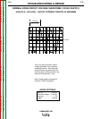
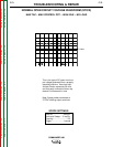
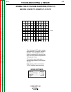
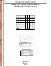
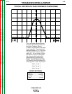
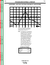
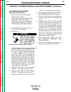
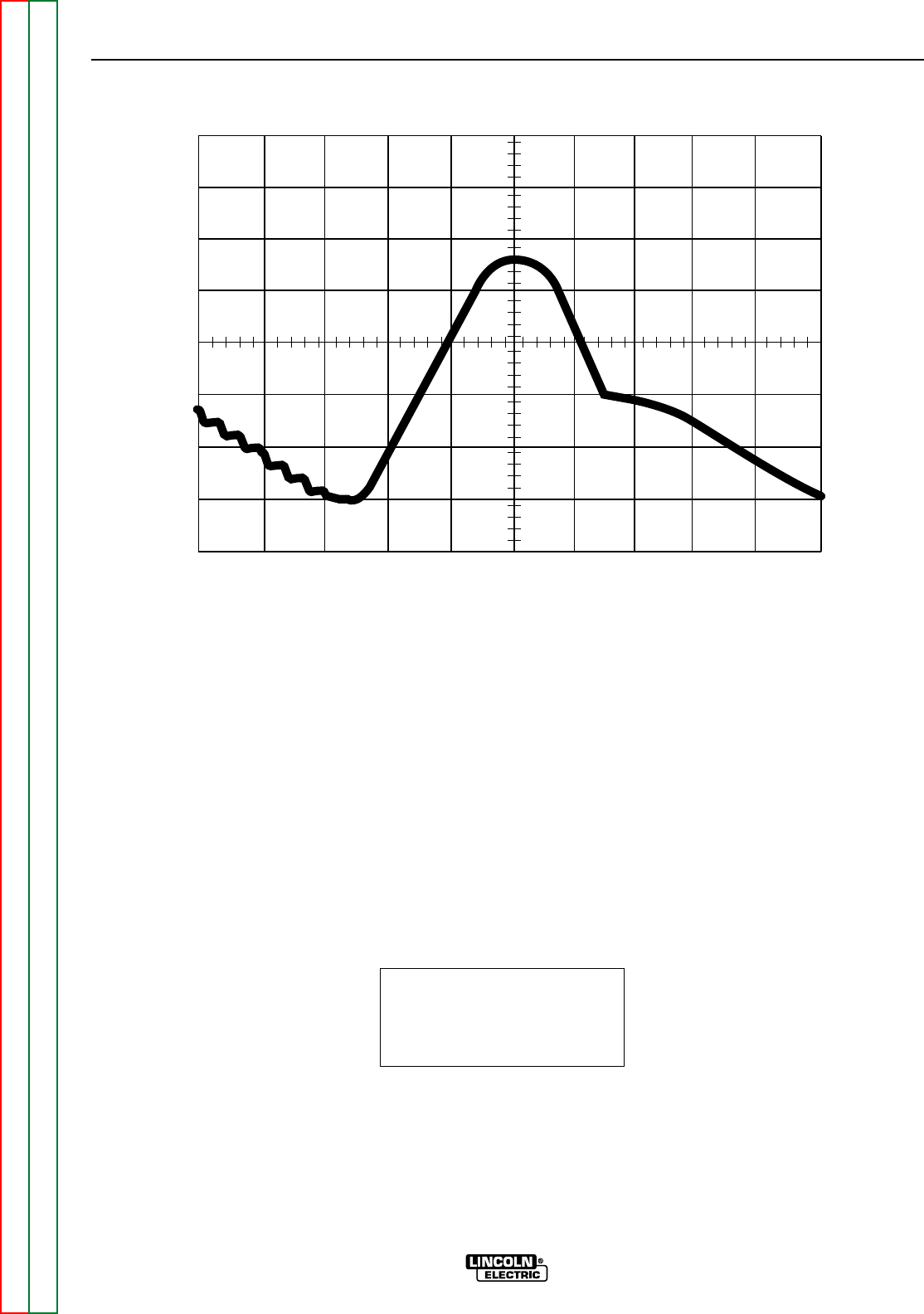
ABNORMAL EXCITER VOLTAGE FEEDBACK WAVEFORMS
1 V
2 ms
This is an example of a bad wave-
form at one of the Exciter Module
outputs (J4 pin 3 to pin 7).
Note: The distortion in the waveform
that causes the period to be in
excess of 9.5 ms. Any distor-
tion that causes a period in
excess of 9.0 ms requires the
Exciter Module to be replaced.
This distorted waveform can
cause machine shutdowns
with “CSS”, “ECL”, & “ECH”
error codes on the display,
and can cause “CRS” and “---”
error codes at power-up. It
can also cause flare-ups and
welds that are too hot, “spat-
tery”, or “cannon balling”.
SCOPE SETTINGS
Volts/Div.......................1V/Div.
Horizontal ..................2ms/Div.
Coupling.............................DC
Trigger.........................Internal


