


Return to Section TOC Return to Section TOC Return to Section TOC Return to Section TOC
Return to Master TOC Return to Master TOC Return to Master TOC Return to Master TOC
F-11 F-11
COMMANDER 400
TROUBLESHOOTING & REPAIR
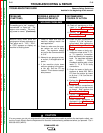
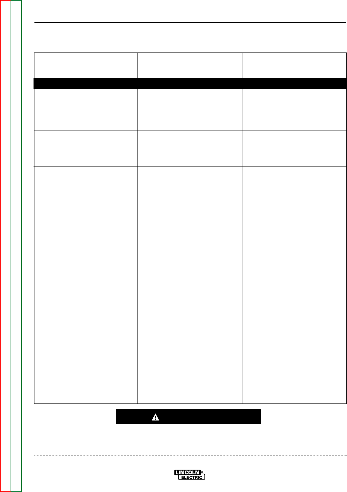
TROUBLESHOOTING GUIDE Observe Safety Guidelines
detailed in the beginning of this manual.
CAUTION
If for any reason you do not understand the test procedures or are unable to perform the test/repairs safely, con-
tact the Lincoln Electric Service Department for electrical troubleshooting assistance before you proceed. Call 1-
800-833-9353 (WELD).
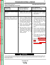
PROBLEMS
(SYMPTOMS)
POSSIBLE AREAS OF
MISADJUSTMENT(S)
RECOMMENDED
COURSE OF ACTION
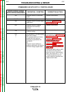
FUNCTION PROBLEMS
The battery does not stay charged. 1. Check for loose, faulty or cor-
roded battery cable connec-
tions.
2. The battery may be faulty.
Check or replace.
1. Perform the Charging Circuit
Test.
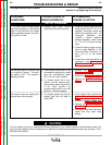
The Fine Control on the
Commander 400 does not work
properly.
1. Make sure the Remote/Local
switch (S1) is in the “LOCAL”
position.
1. Perform the Fine Control
Potentiometer Test.
3. The control board may be faulty.
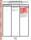
The wire feeder does not work
when connected to the machine’s
14 pin amphenol.
1. Check the circuit breaker CB5.
Reset if tripped.
2. The wire feeder control cable
may be faulty. Check or
replace.
3. The wire feeder may be faulty.
Check or replace.
1. With the engine at high idle
speed: Check for the presence
of 115VAC at leads #31 pin “J”
and #32 pin “A” at the 14 pin
amphenol. If the voltage is
missing or low, Check for loose
or broken connections. See the
Wiring Diagram. Also check
CB5 for proper operation.
2. The RF bypass board (CV mod-
ules only) may be faulty. See
the Wiring Diagram.
3. Perform the Stator Voltage Test.
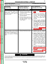
Remote output control not function-
ing correctly.
1. Make sure the Remote/Local
switch (S1) is in the “REMOTE”
position.
2. The remote control unit or cable
may be faulty. Repair or
replace.
1. Perform the Fine Control
Potentiometer Test.
2. Check the Remote/Local switch
(S1) and associated leads. See
the Wiring Diagram.
3. The RF Bypass PC Board (CV
models) may be faulty. See the
Wiring Diagram.
The Remote Protection PC
Board (Stick models) may be
faulty. See the Wiring Diagram.
4. Check amphenols and asso-
ciated leads. See the Wiring
Diagram.